Novel electromagnetic induction heating device

A technology of electromagnetic induction heating and electromagnetic induction coil, applied in the field of new electromagnetic induction heating devices, can solve the problems of energy waste, difficult to meet use requirements, complex structure, etc., and achieve the effect of saving electric energy

Inactive Publication Date: 2018-11-30
上海菱跃工贸有限公司
View PDF15 Cites 0 Cited by
  • Summary
  • Abstract
  • Description
  • Claims
  • Application Information

AI Technical Summary

Problems solved by technology

[0002] Electromagnetic heating technology has been widely used in the field of water heating. The original electromagnetic heating device is only equipped with electromagnetic heating. Once the heating is stopped, the water temperature cools down rapidly, resulting in waste of energy. In order to solve this problem, the Chinese invention patent CN106918070A discloses a The thermal storage heat transfer oil heating system with a built-in electromagnetic heater includes a thermal storage oil tank with an insulating layer, an electromagnetic heater, a heating device and an electric control box. It is characterized in that: the electromagnetic heater consists of a main electromagnetic heater, The auxiliary electromagnetic heater is composed of an auxiliary electromagnetic heater. The main electromagnetic heater includes a magnetically permeable shell, non-magnetically permeable supports and electromagnetic induction coils arranged at both ends of the magnetically permeable shell, and a water-cooled The power tube radiator, the electromagnetic induction coil on the auxiliary electromagnetic heater and the circulating water pump are electrically connected to the electric control box respectively, and it stores heat by setting a special heat storage oil tank, but it still has the following disadvantages: complex structure, low cost High, and the heat storage and heat release process takes a long time, it is difficult to meet the requirements of use, more importantly, the existing coil is a circular coil, because the contact surface between the circular copper wires is small, the magnetic wave induction efficiency will be low In order to achieve the required power, there is also the trouble of increasing the length of the round copper wire, which will cause the temperature inside the tube to rise and cause line failure.

Method used


Image

  • Novel electromagnetic induction heating device
  • Novel electromagnetic induction heating device

Examples


Embodiment Construction

[0014] The principles and features of the present invention are described below in conjunction with the accompanying drawings, and the examples given are only used to explain the present invention, and are not intended to limit the scope of the present invention.

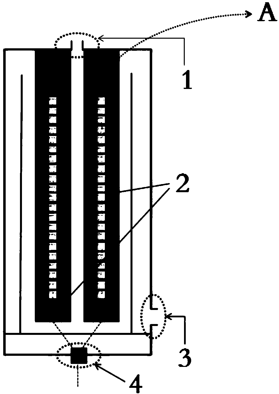
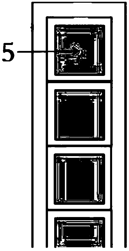
[0015] Such as figure 1 As shown, a novel electromagnetic induction heating device includes a casing and a water outlet 1 located above the casing, a water inlet 3 located below the side of the casing, and a supporting plate is provided below the inside of the casing, and the supporting plate and the bottom plate of the casing form an accommodating The sealed cavity of the power supply part 4, the power supply part 4 communicates with the electromagnetic induction coil formed by the square copper alloy wire 5 located above the supporting plate to generate heat through conduction, and the upper part of the supporting plate is provided with an upper opening composed of a cylindrical partition After the water enters th...


PUM


Abstract

The invention relates to a novel electromagnetic induction heating device which comprises a shell, a water outlet located above the shell and a water inlet located below the shell, a support plate isarranged on the lower side of the interior of the shell, the support plate and the base plate of the shell form a sealing cavity for accommodating a power supply part, and the power supply part is connected with an electromagnetic induction coil formed by a square copper alloy coil above the support plate to conduct electricity and generate heat. The square copper alloy coil increases the efficiency of electromagnetic induction to induce water movement, namely increases the rate of warming; tested parameters show that the heat generated by a round copper coil is below 95%, and heat energy generated by the square copper alloy coil is up to 99.6% in effect; the power supply stops automatically when the water temperature reached the set temperature, the water temperature begins to drop gradually normally, however the water continuous to get the transfer temperature due to the action of research and development of a heat storage device, and rate of temperature dropping is sustained while the temperature rises in a certain range; the heat generated by 30% of electric energy is equivalently achieved, and 30% of electricity energy is saved.

Description

technical field [0001] The invention relates to the field of water heating devices, in particular to a novel electromagnetic induction heating device. Background technique [0002] Electromagnetic heating technology has been widely used in the field of water heating. The original electromagnetic heating device is only equipped with electromagnetic heating. Once the heating is stopped, the water temperature cools down rapidly, resulting in waste of energy. In order to solve this problem, the Chinese invention patent CN106918070A discloses a The thermal storage heat transfer oil heating system with a built-in electromagnetic heater includes a thermal storage oil tank with an insulating layer, an electromagnetic heater, a heating device and an electric control box. It is characterized in that: the electromagnetic heater consists of a main electromagnetic heater, The auxiliary electromagnetic heater is composed of an auxiliary electromagnetic heater. The main electromagnetic hea...

Claims


Application Information

Patent Timeline
Patent Type & Authority Applications(China)
IPC IPC(8): F24H7/02F24H9/18
CPCF24H7/0233F24H9/1818F24H2250/08
Inventor 朴成泽金灿
Owner 上海菱跃工贸有限公司
Why Eureka
Try Eureka