Stroboscopic lamp and assembly method thereof

An assembly method and strobe light technology, applied in the field of strobe lights, can solve the problems of cumbersome parts production processes, high logistics and storage costs, and prone to bump deformation, etc., to achieve increased heat dissipation, performance and cost optimization, and simple structure Effect

Inactive Publication Date: 2019-06-07
慈溪市万诚纺织品有限公司
View PDF0 Cites 0 Cited by
  • Summary
  • Abstract
  • Description
  • Claims
  • Application Information

AI Technical Summary

Problems solved by technology

Its principle structure is limited, and the product strength is poor. The application method is mainly used in a stable and static environment, such as a computer CPU radiator
The strength of the product is poor, and the market application environment is limited; 2. Because the existing technology mainly conducts heat through heat pipes, the diameter of the pipe, the performance of the cooling medium, and the size of the heat sink directly affect the heat dissipation of the product, so the size is often 3. In terms of production technology, the Mohs hardness of aluminum is about 2.75, and its heat sink is very thin, and it is easy to be bumped and deformed during the assembly process, resulting in a greatly reduced product yield and high labor production costs; its products The parts are basically aluminum heat sinks, copper tubes, cooling medium, fixing parts, etc. The heat pipe components mainly include four parts: tube shell, end cover, liquid-absorbing core, and waist plate
The production process of parts is cumbersome and the cost of materials is high (including inconvenient installation)
There are many types of parts, and the refrigeration medium also requires certain requirements for storage, so the cost of logistics and storage is high

Method used


Image

  • Stroboscopic lamp and assembly method thereof
  • Stroboscopic lamp and assembly method thereof
  • Stroboscopic lamp and assembly method thereof

Examples


Embodiment 1

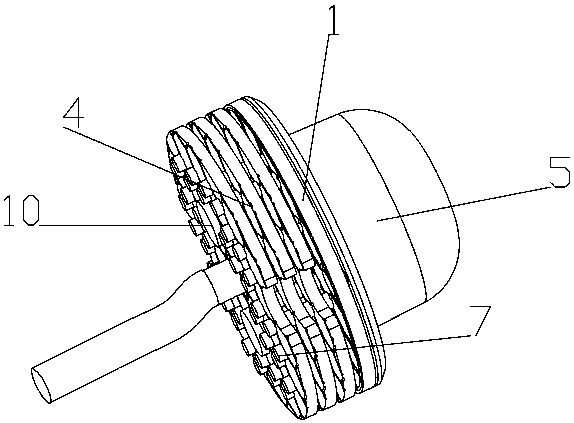
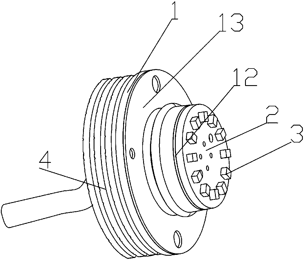
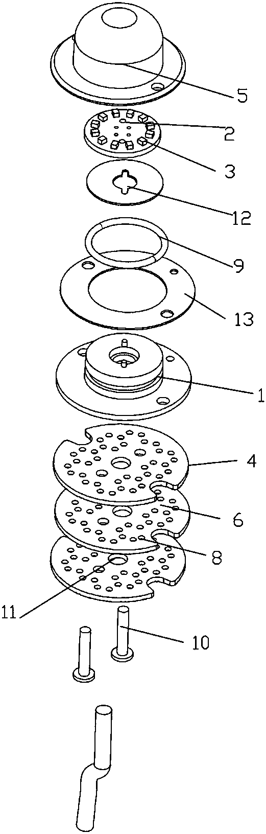
[0026] Such as Figure 1-Figure 4 The strobe light provided in this embodiment includes a mounting base 1, a circuit board 2, an LED lamp bead 3, a cooling assembly 4, a mask 5 and a silicon film 12, and the LED lamp bead 3 is arranged on the circuit board 2, The circuit board 2 is arranged on the upper end of the installation base 1 through the silicon rubber sheet 12, the cover 5 is connected to the upper end of the installation base 1, the heat dissipation assembly 4 is arranged on the lower end of the installation base 1, and the heat dissipation assembly 4 is composed of several heat dissipation components. The fins 6 are spliced ​​together, one end surface of the heat sink 6 is provided with several heat dissipation bumps 7, and the other end surface of the heat sink 6 is matched with the heat dissipation bumps 7 and the heat dissipation grooves 8 are arranged. The heat dissipation bumps 7 are arranged in a honeycomb structure, the plurality of heat dissipation grooves 8...


PUM


Abstract

The invention discloses a stroboscopic lamp and an assembly method thereof. The stroboscopic lamp includes an installation base, a circuit board, an LED lamp bead, a heat dissipation assembly, a coverand a silicon film. The LED lamp bead is arranged on the circuit board, the circuit board is arranged at the upper end of the installation base through the silicone film, the cover covers and is connected with the upper end of the installation base, the heat dissipation assembly is arranged at the upper end of the installation base, and the heat dissipation assembly is formed by splicing severalcooling fins. According to the provided stroboscopic lamp, heat conduction is achieved through heat dissipation convex points between the cooling fins, the design of the heat dissipation convex pointsensures air circulation and the heat dissipation area, and thus the product can achieve the optimal heat conduction and heat dissipation effects. According to the heat dissipation requirement of theproduct, the product is combined by overlapping the cooling fins and fixedly connected through screws, in this way, the structure is simple, installation is convenient, and damaged cooling fins are easily replaced.

Description

technical field [0001] The invention relates to a lamp, in particular to a strobe lamp. Background technique [0002] The strobe light is a kind of decorative and warning lamp that has only recently appeared in the world. The strobe light has many uses: it can be used as a warning light for special vehicles; it can be installed on the top or edge of a tall building to make the building look magnificent at night; The flashes are particularly eye-catching and safer. The LED strobe lighting module is much superior to the light bulb light source and flash light light source commonly used in the past. It has long life (50,000 hours), wide viewing angle, anti-vibration, easy circuit control, less heat generation, energy saving, and It has the characteristics of dynamic, convenient installation and safe use. [0003] But existing strobe light has following shortcoming: 1, the technical scheme of existing product is heat pipe conduction at present, and it has utilized the heat co...

Claims


Application Information

Patent Timeline
Patent Type & Authority Applications(China)
IPC IPC(8): F21S10/06F21V31/00
Inventor 陈君辉
Owner 慈溪市万诚纺织品有限公司
Why Eureka
Try Eureka