Water-saving environment-friendly cooling tower

A cooling tower and environment-friendly technology, applied in the field of cooling towers, can solve the problems of inconvenient operation, manual adjustment, inability to achieve cooling of high-temperature gas, etc., and achieve the effect of convenient adjustment and saving cooling water.

Pending Publication Date: 2018-11-30
德州贝泰制冷设备有限公司
View PDF0 Cites 6 Cited by
  • Summary
  • Abstract
  • Description
  • Claims
  • Application Information

AI Technical Summary

Problems solved by technology

[0004] The current wet cooling tower continuously sprays the high-temperature gas during work, and generates heat exchange through the intersection between high-temperature gas and low-temperature water vapor. After heat exchange, the high-temperature water is discharged through the drain pipe at the bottom. After cooling The gas is discharged through the fan at the upper end of the cooling tower. In the actual operation of the cooling tower, the fan and the water spray system need to work continuously, and the cooling power cannot be adjusted according to the actual cooling needs. When the amount of high-temperature gas is small or the temperature is low When the temperature is high, a small amount of

Method used


Image

  • Water-saving environment-friendly cooling tower
  • Water-saving environment-friendly cooling tower
  • Water-saving environment-friendly cooling tower

Examples


Example Embodiment

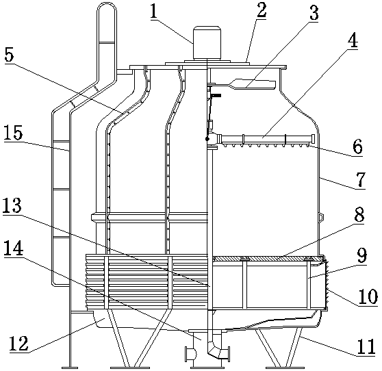
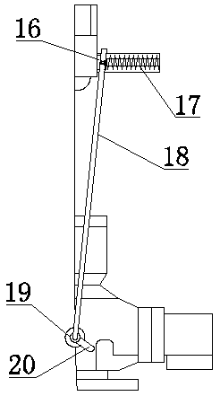
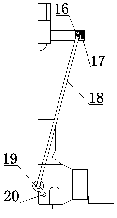
[0025] In Embodiment 1, a water-saving and environmentally friendly cooling tower includes an upper tower body 7 and a lower tower body 12, and is characterized in that: the upper tower body 7 has an upper end opening, and a fan support 2 is installed at the position of the upper end opening. , a motor reducer 1 is installed on the fan support 2, the lower end of the motor reducer 1 is installed with symmetrically distributed fan blades 3, and a spray system is installed in the middle position of the upper tower body 7, The spray system includes a water inlet pipe 13, a spray pipe 4 connected to the water inlet pipe 13, and a nozzle 6 installed on the spray pipe 4. There is also a gap between the rotating shaft at the lower end of the motor reducer 1 and the water inlet pipe 13. An adjustment device for controlling the amount of spray water is provided. The adjustment device includes a moving slider 16 installed at the lower end of the motor reducer shaft. The moving slider 16 ...


PUM


Abstract

The invention discloses a water-saving environment-friendly cooling tower which comprises an upper tower body and a lower tower body. An opening is formed in the upper end of the upper tower body, a fan support is installed at the position of the opening in the upper end and provided with a motor reducing gear, the lower end of the motor reducing gear is provided with symmetrically-distributed fanblades, a spraying system is installed in the middle inside the upper tower body, the spraying system comprises a water inlet pipe, a spraying pipe connected with the water inlet pipe and a nozzle installed on the spraying pipe, an adjusting device for controlling the spraying water amount is arranged between a rotating shaft at the lower end of the motor reducing gear and the water inlet pipe, the adjusting device comprises a movable sliding block installed at the lower end of the rotating shaft of the motor reducing gear, the movable sliding block is movably installed on one side of the rotating shaft of the motor reducing gear through a cylindrical guide rail, and a spring is arranged between the movable sliding block and the guide rail. According to the cooling tower, the spraying water amount can be controlled without labor only by setting the adjusting device according to experience in practical work and controlling the rotating speed of a fan.

Description

technical field [0001] The invention relates to the technical field of cooling towers, in particular to a water-saving and environment-friendly cooling tower, which is applied to cooling in industrial equipment. Background technique [0002] The cooling tower is a cooling device that sprays circulating cooling water in it to make it in direct contact with the air, and dissipates the carried heat into the atmosphere through evaporation and convection. It is a device that uses the evaporative heat absorption principle of water to dissipate the waste heat generated in industry or refrigeration and air conditioning to ensure the operation of the system. The cooling tower can lower the temperature of the cooling water. [0003] The working principle of the wet cooling tower is that the circulating water spread on the surface of the filler is in direct contact with the air, and the heat of the water is transferred to the air through contact heat transfer and evaporation heat dissi...

Claims


Application Information

Patent Timeline
IPC IPC(8): F28C1/02F28F25/06F28F25/08F28F25/10F28F25/12F28F27/00
CPCF28C1/02F28F25/06F28F25/08F28F25/10F28F25/12F28F27/003
Inventor 袁文军袁金朋
Owner 德州贝泰制冷设备有限公司
Why Eureka
Try Eureka