Supercharge Your Innovation With Domain-Expert AI Agents!

A method for measuring gas pressure

A gas pressure and measurement method technology, applied in the field of aerodynamics, can solve the problems of complex manufacturing process of pressure measuring paint and high cost of pressure fluorescent probes, and achieve the effects of low price, low cost and shortened response time

Active Publication Date: 2019-09-13
CHANGCHUN INST OF APPLIED CHEMISTRY - CHINESE ACAD OF SCI
View PDF6 Cites 0 Cited by
  • Summary
  • Abstract
  • Description
  • Claims
  • Application Information

AI Technical Summary

Problems solved by technology

[0003] Therefore, in view of the disadvantages of traditional pressure fluorescent probes in the existing PSP technology, such as high cost, a certain oxygen exchange time, and complicated manufacturing process of pressure measuring coatings, it is necessary to provide a low-cost measurement, short response time, and richer and more diverse coating processes. pressure measuring coating

Method used


Image

  • A method for measuring gas pressure
  • A method for measuring gas pressure
  • A method for measuring gas pressure

Examples


Embodiment 1

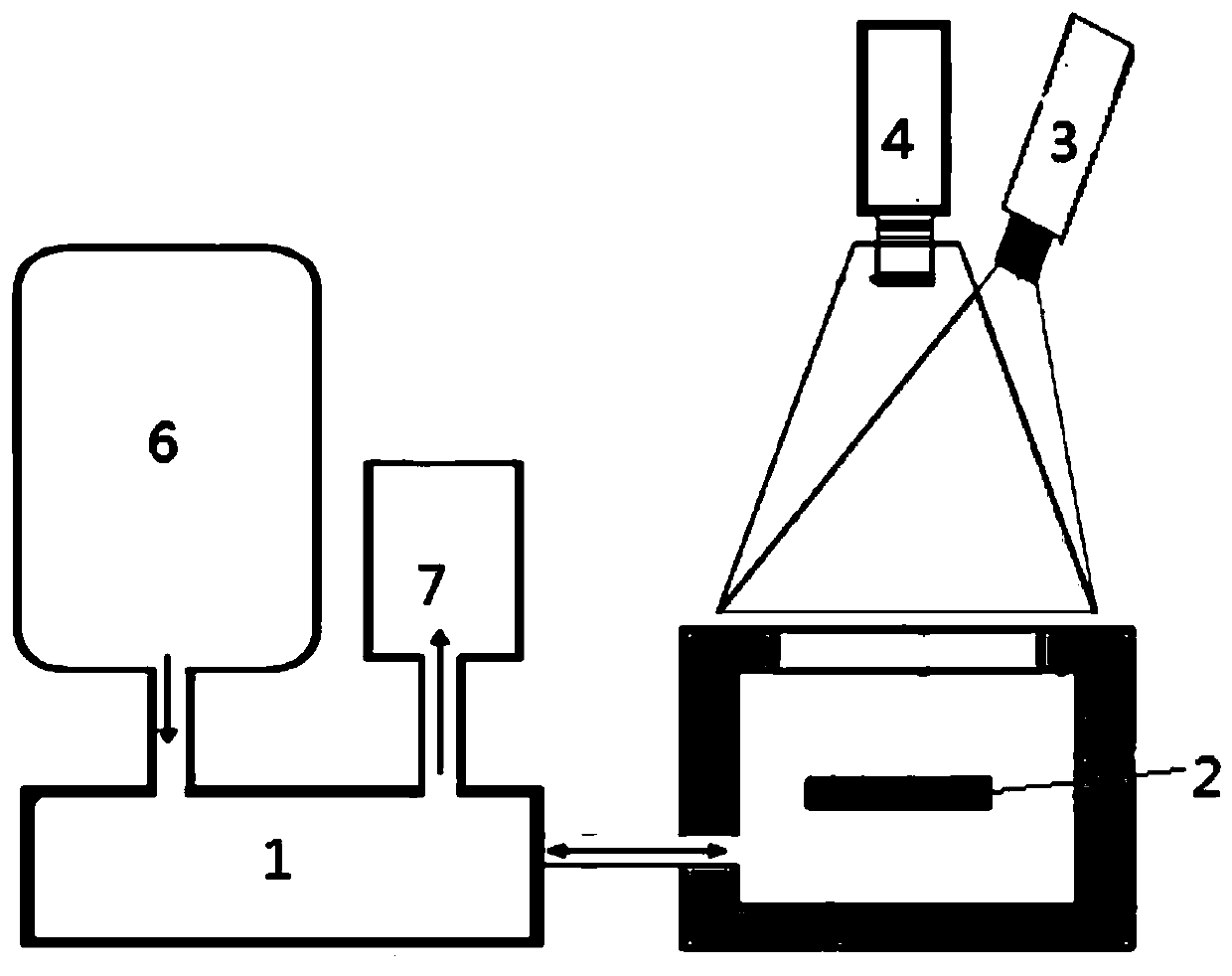
[0057] A gas pressure of 1 MPa is applied to the outer surface of the object to be measured, and the afterglow intensity changes are monitored at different stages of afterglow attenuation. From the results, it can be found that there is a regularity in the afterglow intensity changes at different stages. The pressure response of the afterglow material is the most sensitive in the decay time range of 150-250 seconds. The results are as follows image 3 As shown, image 3 This is the response result of the attenuation to the same pressure (1Mpa) measured at different times in Example 1 of the present invention.

Embodiment 2

[0059] In the afterglow interval where the afterglow intensity decays to 5% to 30% of the initial brightness, the same external gas pressure acts on the surface of the afterglow material, and the afterglow intensity change is linearly related to the attenuation degree, and the result is as follows Figure 4 As shown, Figure 4 It is the result curve of brightness attenuation to the initial afterglow brightness between 28% and 8%.

Embodiment 3

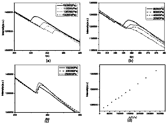
[0061] When the afterglow progresses to 240 seconds, when 20000, 40000, 60000, 80000, 100500, 110000, 130000, 150000, 190000, 230,000, 280000Pa gas pressure is applied to the surface of the afterglow material, the brightness change of the afterglow material is linearly related to the pressure. Thus, through the measurement of the afterglow brightness change, the standard curve of the measured gas pressure is obtained, and the result is as Figure 5 As shown, Figure 5 This is the standard curve of measuring gas pressure and the pressure-afterglow intensity result obtained in Example 3 of the present invention. Among them, (a) 20000, 40000, 60000, 80000 (b) 100500, 110000, 130000, 150000 (c) 190000, 230,000, 280000 (d) pressure vs. afterglow intensity change fitting curve.


PUM

PropertyMeasurementUnit
thicknessaaaaaaaaaa
wavelengthaaaaaaaaaa

Abstract

The invention provides a method for measuring gas pressure, comprising: placing a long afterglow material on the surface of an object to be measured, using an excitation light source to excite the long afterglow material on the surface of the object to be measured; applying a known gas to the surface of the object to be measured after excitation Pressure, the standard working curve of the surface pressure of the object to be measured is obtained by using the response of the afterglow intensity change of the long afterglow material to the known gas pressure; the unknown gas pressure is applied to the object to be measured to obtain the afterglow intensity change, and the afterglow intensity change and the gas pressure The correlation of the correlation with the standard working curve is compared to obtain the gas pressure on the surface of the object to be measured. The invention adopts the inorganic long afterglow material to replace the metal-organic complex fluorescent probe in the traditional pressure-sensitive paint, and has low cost and good stability. The invention adopts that the change of the surface pressure of the object to be measured leads to the change of the trap distribution of the afterglow material, resulting in the change of its luminous brightness, the measurement is simple, and the result is accurate; meanwhile, the pressure response time of the afterglow material is short.

Description

Technical field [0001] The invention relates to the technical field of aerodynamics, in particular to a method for measuring gas pressure. Background technique [0002] In many cases in the field of measurement and control, it is necessary to measure the instantaneous pressure on the surface of the object to be measured. At present, there are two more common solutions. The first is a more traditional pressure measurement method, by manufacturing expensive special pressure measurement models. In addition, a series of dedicated pressure measuring holes are opened on the surface of the model to measure the intermittent point pressure. The other is to apply pressure sensitive paint (PSP: pressure sensitive paint) to the surface of the tested model. The pressure sensitive paint can react the pressure caused by the airflow to the change of fluorescence intensity, and pass the non-contact type The optical measurement method measures the surface pressure distribution of the measured are...

Claims


Application Information

Patent Timeline
Patent Type & Authority Patents(China)
IPC IPC(8): G01L11/02C09K11/64
Inventor 李成宇李达庞然张粟姜丽宏刘贯宇
Owner CHANGCHUN INST OF APPLIED CHEMISTRY - CHINESE ACAD OF SCI
Features
  • R&D
  • Intellectual Property
  • Life Sciences
  • Materials
  • Tech Scout
  • Unparalleled Data Quality
  • Higher Quality Content
  • 60% Fewer Hallucinations
Learn More