

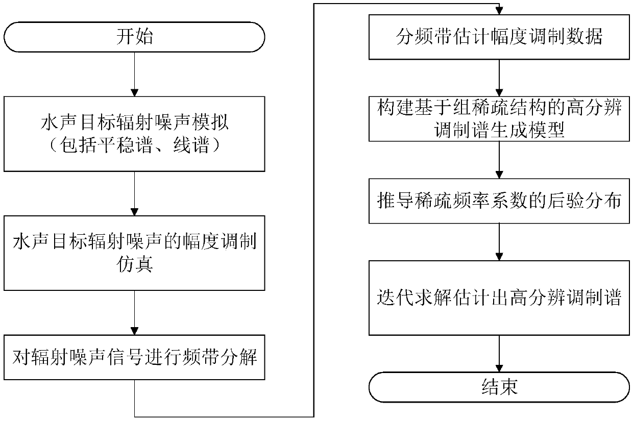
Underwater acoustic target radiation noise modulation spectrum reconstruction method based on group sparse structure
A radiated noise, group sparse technology, applied in radio wave measurement systems, instruments, etc., can solve the problems of unused sub-band modulation spectrum correlation between sub-bands, missing important frequency domain information of signals, and inability to detect spectral lines.
- Summary
- Abstract
- Description
- Claims
- Application Information
AI Technical Summary
Problems solved by technology
Method used
Image

Examples
Embodiment 1
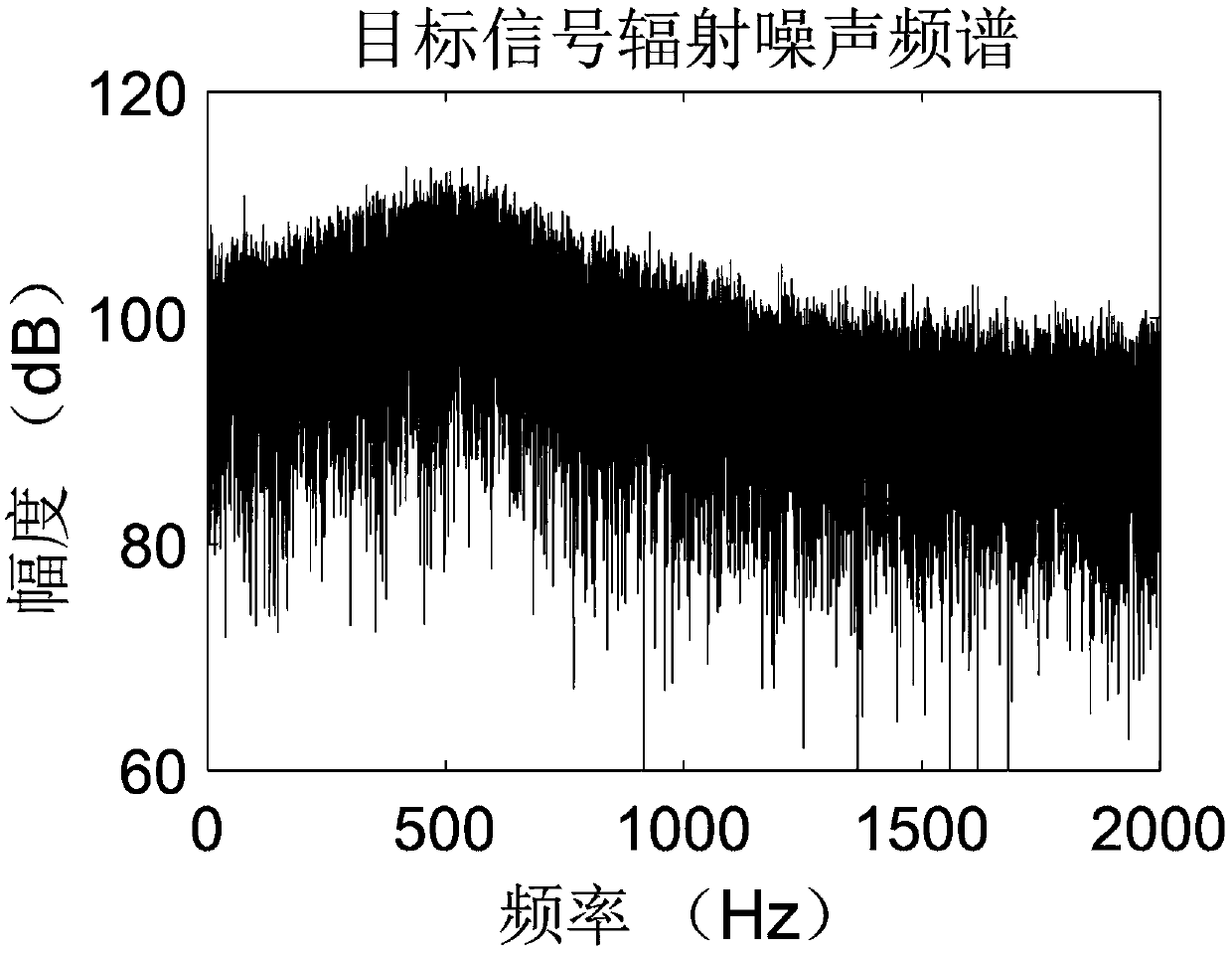
[0152] In this embodiment, the sampling frequency F s = 4kHz. Using the three-parameter model method to simulate the power spectrum Gxf of the stationary continuum of the radiated noise of underwater acoustic targets, the three parameters are set as follows during the simulation process: sharpness factor ω m =200Hz, spectral peak center position factor ω c =500Hz, the relative proportional influence factor λ=0 of the spectrum high and low frequency band amplitudes, and the signal energy of the smooth continuous spectrum σ=500.
[0153] Simulate the 3 line spectral components of target radiated noise: Set the frequency f of the sinusoidal signal i Respectively 20Hz, 50Hz, 100Hz and the corresponding 4th harmonic line spectrum. The observation time is T=10s. The target radiation noise signal R(t) is obtained by adding the stationary continuum component and the line spectrum component. The spectrum of the target radiated noise signal is as figure 2 shown.
[0154] In this...
PUM
 Abstract
Description
Claims
Application Information