
Novel heat dissipation system based on heat dissipation housing

A technology of heat dissipation shell and heat dissipation system, which is applied in the directions of instruments, electrical digital data processing, digital data processing parts, etc. Simple, easy-to-use effects

Inactive Publication Date: 2018-11-30
中江本富电子科技有限公司
View PDF0 Cites 1 Cited by
  • Summary
  • Abstract
  • Description
  • Claims
  • Application Information

AI Technical Summary

Problems solved by technology

[0004] The technical problem to be solved by the present invention is that the existing shell cannot effectively dissipate heat, the heat dissipation of the device is poor, and it is not convenient for long-term use. The purpose is to provide a new heat dissipation system based on the heat dissipation shell and solve the problem of using the heat dissipation shell

Method used


Image

  • Novel heat dissipation system based on heat dissipation housing
  • Novel heat dissipation system based on heat dissipation housing

Examples


Embodiment 1

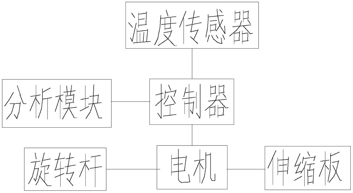
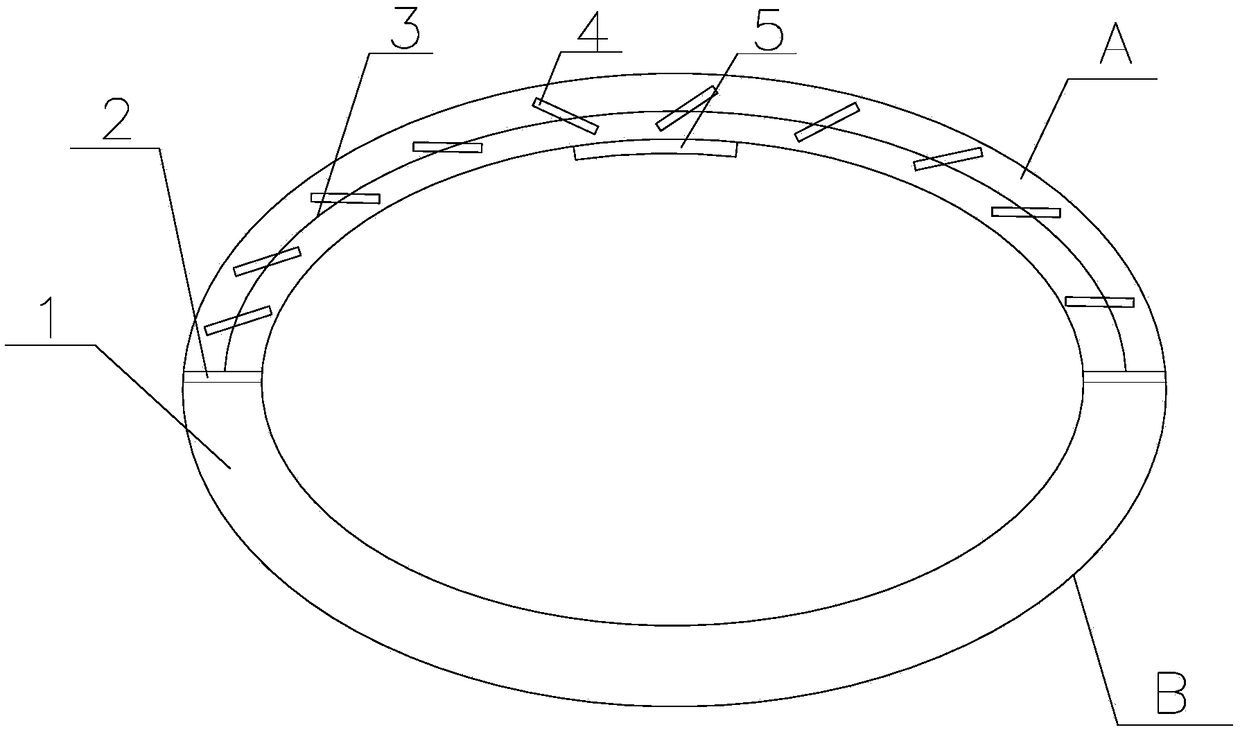
[0024] Such as Figure 1~2 As shown, the present invention is based on a novel heat dissipation system of a heat dissipation shell, including a shell 1, the shell 1 is an elastic rubber ring structure with a hollow inside, and a partition plate 2 is arranged inside the shell 1, and the partition plate 2 will The inner cavity of the housing 1 is evenly divided into two circular arc structures, A and B. A connecting rod 3 is arranged in part A of the housing 1, and a plurality of rotating rods 4 are connected to the connecting rod 3. Part A rotates along the connecting rod 3, liquid paraffin is housed in the part A, and some through holes are set on the partition plate 2, and a telescopic plate for blocking the through holes is provided on the partition plate 2, and one end of the telescopic plate is connected to the One end of the partition board is flush, and the other end is telescopic along the plane where the partition board is located; a temperature sensor 5 is arranged on...

Embodiment 2

[0026] On the basis of embodiment 1, including a shell, the shell is provided with a controller, the controller is connected with a temperature sensor, a motor, the motor is connected with a telescopic plate, and the controller is connected with an analysis module; the temperature sensor is connected with On the casing, the motor is used to control the expansion and contraction of the expansion plate. When the temperature detected by the temperature sensor is higher than 30 degrees, the controller controls the motor to work, and the motor controls the expansion plate to shorten, so that the through hole on the partition plate is exposed; when the temperature sensor detects When the temperature is lower than 30 degrees, the controller controls the motor to work, and the motor controls the expansion plate to extend, so that the liquid paraffin in the shell is in the A part. The motor is also connected with a rotating rod. When the temperature detected by the temperature sensor is...


PUM

PropertyMeasurementUnit
Thicknessaaaaaaaaaa

Abstract

The invention discloses a novel heat dissipation system based on a heat dissipation housing, which comprises the housing. A controller is arranged on the housing; the controller is connected with a temperature sensor and a motor; the motor is connected with a telescopic plate; the controller is connected with an analysis module; the temperature sensor is connected onto the housing; the motor is used for controlling the telescopic plate to extend and retract; when a temperature detected by the temperature sensor is higher than 30 DEG C, the controller controls the motor to work, and the motor controls the telescopic plate to retract so as to expose out a through hole on a separator; when the temperature detected by the temperature sensor is lower than 30 DEG C, the controller controls the motor to work, and the motor controls the telescopic plate to extend, so that liquid paraffin in the housing is at an A part. The novel heat dissipation system is simple in structure and convenient tooperate and use when in use.

Description

technical field [0001] The invention relates to the field of heat dissipation, in particular to a novel heat dissipation system based on a heat dissipation shell. Background technique [0002] The heat dissipation methods include radiation heat dissipation, conduction heat dissipation, convection heat dissipation, and evaporative heat dissipation. The radiator absorbs heat in the computer, and then dissipates it to the inside or outside of the chassis to ensure that the temperature of the computer components is normal. Integrated circuits are heavily used in computer components. As we all know, high temperature is the enemy of integrated circuits. High temperature will not only lead to unstable operation of the system, shorten the service life, and may even burn some components. The heat that causes high temperature does not come from outside the computer, but from inside the computer, or inside the integrated circuit. The function of the radiator is to absorb the heat a...

Claims


Application Information

Patent Timeline
IPC IPC(8): G06F1/20G06F11/30
CPCG06F1/206G06F11/3058
Inventor 陈炳
Owner 中江本富电子科技有限公司
Learn More