Flexible microwave directional coupler with controllable coupling degree

A directional coupler and coupler technology, applied in the field of radio frequency and microwave, can solve the problems of inflexibility of couplers, inflexible and simple coupling design, etc., and achieve the effect of good bendability, flexible design, and reliable and flexible characteristics.

CN108923108AInactive Publication Date: 2018-11-30XIDIAN UNIV
2 Cites 6 Cited by

Patent Information

Authority / Receiving Office
CN · China
Patent Type
Applications(China)
Current Assignee / Owner
Publication Date
2018-11-30
Estimated Expiration
Not applicable · inactive patent

Smart Images

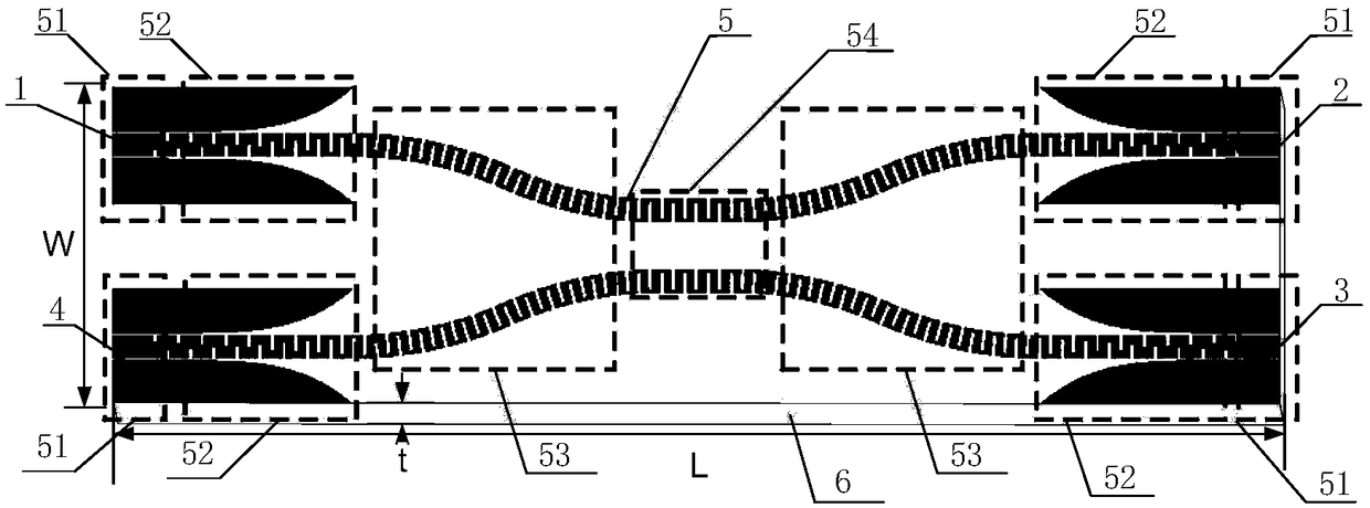
  • Figure 1
    Figure 1
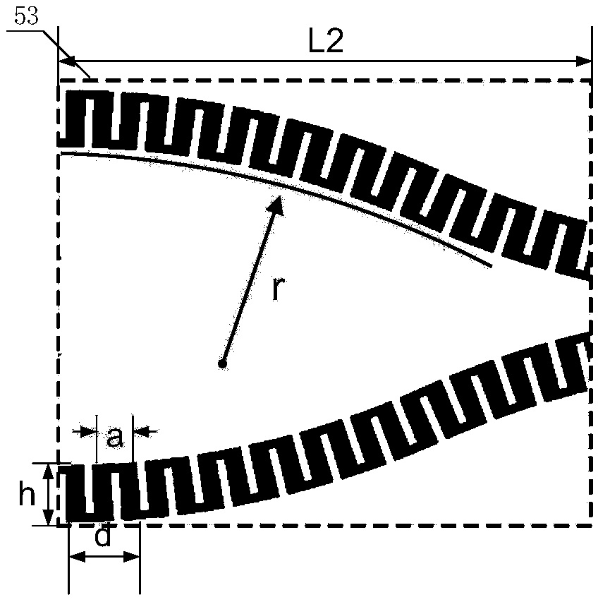
  • Figure 2
    Figure 2
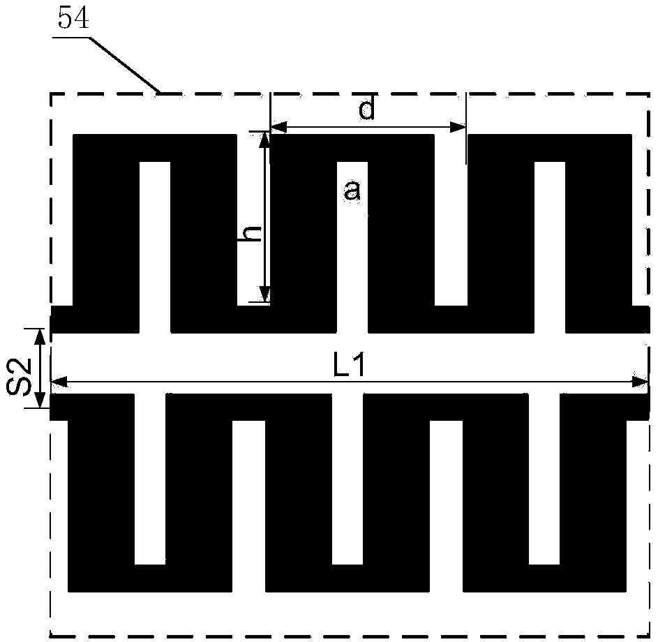
  • Figure 3
    Figure 3
Patent Text Reader

Abstract

The invention provides a flexible microwave directional coupler with a controllable coupling degree. The problems that an existing coupler cannot realize flexibility, and the coupling degree is not easy and inconvenient to adjust and control are mainly solved. The flexible microwave directional coupler comprises a flexible dielectric plate (6) and a conductor layer (5) etched on the dielectric plate; the conductor layer comprises a feed structure (51), a mode conversion structure (52), a connecting structure (53) and a coupling structure (54); the dielectric plate adopts a flexible dielectricmaterial as a substrate of the coupler, so that the flexible characteristic is achieved; the mode conversion structure is used for completing conversion of transmission modes, and better impedance matching is achieved; the connecting structure is constituted by a pair of curved artificial surface plasmon transmission lines, and thus dependence of transmission of electromagnetic energy on a metal floor is avoided; and the coupling structure is constituted by a pair of mutually-parallel artificial surface plasmon transmission lines and used for realizing parallel coupling. According to the flexible microwave directional coupler, the coupling degree of the coupler is increased, flexible adjusting and control of the coupling degree are achieved, and the flexible microwave directional coupler can be applied to a radio frequency microwave circuit system.
Need to check novelty before this filing date? Find Prior Art

Description

technical field

[0001] The invention belongs to the field of radio frequency and microwave technology, in particular to a flexible microwave directional coupler with controllable coupling degree, which can be used in radio frequency microwave circuit systems. Background technique

[0002] With the rapid development of communication technology, flexible microwave devices are gaining more and more research due to their unique flexibility / extensibility. It is light, thin, soft, bendable, and foldable, which is superior to traditional devices, so it shows great flexibility and broad application space in terms of application.

[0003] In 1992, the first flexible OLED device based on a plastic substrate was successfully prepared by Gustafsson et al., which opened an upsurge in the research of flexible electronic devices. In recent years, the flexible electronics market has expanded rapidly and has become a pillar industry in some countries. Combined with high-efficiency and low-...

Examples

Embodiment 1

[0027] Embodiment 1, a flexible microwave directional coupler working at 6-10 GHz to realize strong coupling.

[0028] see figure 1 , the coupler of this example includes 4 ports, a conductor layer 5 and a dielectric board 6 . The conductor layer 5 passes the conductivity σ=6.301×10 7 The conductor layer 5 includes four feed structures 51 , four mode conversion structures 52 , two connection structures 53 and one coupling structure 54 . Each feed structure 51 is connected with each transition structure 52 to form a structural whole, which are respectively located at the upper left corner, lower left corner, lower right corner and upper right corner of the dielectric board. The coupling structure 54 is located in the center of the dielectric plate, and the two connecting structures 53 are respectively located on the left and right sides of the coupling structure 54, wherein the left end of the connecting structure 53 located on the left side of the coupling structure 54 and t...

Embodiment 2

[0034] Embodiment 2, working at 6-10GHz to realize the flexible microwave directional coupler with controllable coupling degree

[0035] see figure 1 , figure 2 , Figure 4 , the structure of this embodiment 2 is the same as that of embodiment 1, only the coupling gap in the coupling structure 54 has been adjusted:

[0036] see image 3 , in the coupling structure 54, the coupling gap S2 between the parallel coupling lines is sequentially adjusted to 2mm, 4mm, 6mm, 8mm, 10mm, 12mm, 14mm, 16mm, so as to realize the adjustment of the coupling degree.

[0037] Effect of the present invention can be further illustrated by following simulation:

[0038] Simulation 1 simulates the transmission characteristics of the coupler in Embodiment 1 of the present invention, and the results are as follows Figure 5 . Figure 5 The abscissa is the frequency, the unit is GHz, the range is from 4GHz to 10GHz, and the ordinate is the decibel value of the S parameter amplitude, the unit is ...