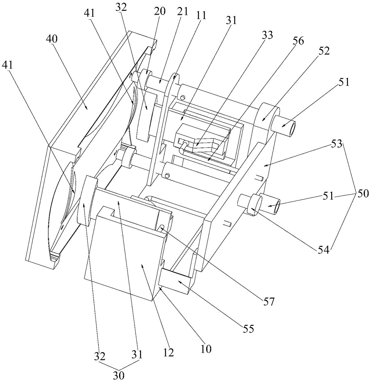
Display plug wire positioning device

A technology of positioning device and display, which is applied to coupling devices, parts of connecting devices, connector applications, etc., can solve problems such as low plug-in efficiency, and achieve the effects of simple structure, easy maintenance, and improved plug-in efficiency.

Pending Publication Date: 2018-11-30
ZHUHAI GREE INTELLIGENT EQUIP CO LTD +1
0 Cites 0 Cited by

AI-Extracted Technical Summary

Problems solved by technology

[0004] The main purpose of the present invention is to provide a monitor plug-in positioning device to at least solve the p...

Method used

Driving part 50 also comprises spring mandrel 57, and spring mandrel 57 is two, and one end of two spring mandrels 57 is connected with two second support plates 12, and the other end of two spring mandrels 57 is connected with two The two positioning arms 31 are connected away from the first end of the display 40 to promote the two positioning arms 31 to swing from the sixth preset position to the fifth preset position, and the spring mandrel 57 can prevent the positioning arms 31 from clamping the display 40. Movement occurs.
The drive portion 50 includes a connecting sleeve 51, which is sleeved on the electric plug 21, and one end of the connecting sleeve 51 has a connecting pin arranged radially thereof; The pin hole extends along the extension direction of the electric plug 21 , and the connecting pin is slidably penetrated in the pin hole to drive the electric plug 21 to move between the third preset position and the fourth preset position. There are two electric plugs 21 and two connecting sleeves 51, and the two electric plugs 21 and the two connecting sleeves 51 are arranged at intervals along the vertical direction. When 21 moves to the third preset position, it is plugged correspondingly with the two power sockets on the display 40, so that the operation of plugging in the display is more convenient.
The plug-in positioning device of the present invention, through the plug-in assembly 20, the positioning assembly 30 is connected with the driving part 50, rea...

Abstract

The invention provides a display plug wire positioning device. The display plug wire positioning device comprises a base, a plug-in assembly, a positioning assembly and a driving part. The plug-in assembly is movably arranged on the base, and is used for being connected with plug-in holes in a display in a plugging mode when a robot moves the display to a first preset position; the positioning assembly is movably arranged on the base, and is used for positioning and locking the display when the robot moves the display to a second preset position; and the driving part is separately connected with the plug-in assembly and the positioning assembly to drive the plug-in assembly and the positioning assembly to act. According to the plug wire positioning device, the problem of low positioning and plug-in efficiency of the display in a manual way when displays are tested in the prior art is solved.

Application Domain

Contact member assembly/disassemblyConnector applications +1

Technology Topic

EngineeringDisplay device +4

Image

  • Display plug wire positioning device

Examples

  • Experimental program(1)

Example Embodiment

[0024] It should be noted that the embodiments of the present invention and the features in the embodiments can be combined with each other if there is no conflict. Hereinafter, the present invention will be described in detail with reference to the drawings and in conjunction with the embodiments.
[0025] In order to enable those skilled in the art to better understand the solutions of the present invention, the technical solutions in the embodiments of the present invention will be described clearly and completely with reference to the accompanying drawings in the embodiments of the present invention. Obviously, the described embodiments are only It is a part of the embodiments of the present invention, not all the embodiments. Based on the embodiments of the present invention, all other embodiments obtained by those of ordinary skill in the art without creative work shall fall within the protection scope of the present invention.
[0026] The present invention provides a display plug-in positioning device, please refer to figure 1 , Used for plugging and positioning the display during plug-in detection. The display plug-in positioning device includes a base 10; the plug-in assembly 20 is movably arranged on the base 10, and the plug-in assembly 20 is used to move the display 40 to the A preset position is plugged into the plug hole on the display 40; the positioning component 30 is movably arranged on the base 10, and the positioning component 30 is used to move the display 40 to the second preset position. 40 is positioned and locked; the driving part 50 is connected to both the plug-in assembly 20 and the positioning assembly 30 to drive the plug-in assembly 20 and the positioning assembly 30 to move without manual wire insertion and positioning, reducing labor costs and increasing detection efficiency.
[0027] Such as figure 1 As shown, in this embodiment, the base 10 is provided with a first support plate 11, and the first support plate 11 is provided with a sliding hole. The plug-in assembly 20 includes an electric plug 21 slidably inserted in the sliding hole. The electric plug has a third preset position that extends forward and a fourth preset position that is retracted backward. When the electric plug 21 is moved to the third preset position, it is plugged into the plug hole on the display 40.
[0028] The driving part 50 includes a connecting sleeve 51 sleeved on the electric plug 21, one end of the connecting sleeve 51 has a connecting pin arranged along its radial direction; wherein the electric plug 21 is provided with a pin hole penetrating in the radial direction, The pin hole extends along the extension direction of the electric plug 21, and the connecting pin is slidably penetrated in the pin hole to drive the electric plug 21 to move between the third preset position and the fourth preset position. There are two electric plugs 21 and two connecting sleeves 51. The two electric plugs 21 and the two connecting sleeves 51 are arranged at intervals in the vertical direction. Among them, there are two electric plug holes on the display 40, and two electric plugs When 21 is moved to the third preset position, it is correspondingly plugged into the two plug holes on the display 40, which makes the operation of plugging in the display more convenient.
[0029] Specifically, in order to realize automatic plug-in, the driving part 50 further includes a connecting beam 52 and a driving plate 53, both ends of the connecting beam 52 are correspondingly connected with the two connecting sleeves 51 to drive the two connecting sleeves 51 to move synchronously. 53 is fixedly connected to the connecting beam 52, wherein the driving plate 53 is provided with a driving seat 54 and the driving plate 53 is connected to the air cylinder through the driving seat 54 so as to drive two connecting beams 52 and two connecting sleeves 51 under the driving of the air cylinder. The electrical plug 21 moves between the third preset position and the fourth preset position, which saves the detection time of the display and saves manual operation.
[0030] The two sides of the base 10 are respectively provided with second support plates 12, and two second support plates 12 are provided with track grooves; wherein, the two sides of the drive plate 53 are respectively provided with linear guide rails 55 matching the track grooves, two linear guides 55 The guide rail 55 is slidably arranged in two rail grooves to move along a straight line under the drive of an air cylinder; the positioning assembly 30 includes a positioning arm 31, and there are two positioning arms 31, and the two positioning arms 31 are swingably arranged on the base 10 On the two second support plates 12 corresponding to the side, the two positioning arms 31 have a fifth preset position and a sixth preset position that swing relatively; wherein, two positioning grooves 41 are provided on the display 40, two positioning When the arm 31 is located at the fifth preset position, the two positioning arms 31 are inserted into the two positioning slots 41 correspondingly. When the two positioning arms 31 are located at the sixth preset position, the two positioning arms 31 clamp the display 40 tightly to achieve alignment. Fixing of the display.
[0031] The end of the positioning arm 31 facing the display 40 has a clamping end; wherein, when the two positioning arms 31 swing toward the fifth preset position, the two clamping ends 32 are close to each other, and the two positioning arms 31 face the sixth preset position. When the setting position swings, the two clamping ends 32 are far away from each other, and when the two positioning arms 31 are located at the fifth preset position, the two clamping ends 32 are inserted into the two positioning grooves 41, and the two positioning arms 31 are located At the sixth preset position, the two clamping ends 32 are clamped correspondingly to the two positioning grooves to ensure that the display is fixed during detection and prevent the positioning arm 31 from continuing to swing toward the sixth preset position.
[0032] The middle part of the positioning arm 31 and the second support plate 12 are hinged to each other to swing the positioning arm 31. The driving part 50 includes a driving rod 56. There are two driving rods 56. The first ends of the two driving rods 56 are connected to the two positioning arms respectively. One end of 31 away from the display 40 is connected to drive the two positioning arms 31 to swing from the fifth preset position to the sixth preset position.
[0033] The ends of the two positioning arms 31 away from the display 40 are each provided with a pin slot 33, wherein the first ends of the two driving rods 56 have tensioning ball heads, and the pulling heads of the two driving rods 56 are embedded in the two positioning heads. The pin groove 33 of the arm 31 drives the two positioning arms 31 to swing from the fifth preset position to the sixth preset position when sliding along the pin groove.
[0034] The drive part 50 also includes a drive plate 53, the second ends of the two drive rods 56 are fixedly connected to the drive plate 53; wherein, the drive plate 53 has a drive seat 54 and the drive plate 53 is connected to the cylinder through the drive seat 54 so as to The two positioning arms 31 are driven to swing by the two driving rods 56 under the driving of the, which realizes automatic control of the positioning of the display and saves operation time.
[0035] The driving part 50 also includes a spring mandrel 57. There are two spring mandrels 57. One end of the two spring mandrels 57 is connected to the two second support plates 12, and the other end of the two spring mandrels 57 is connected to two positioning arms. The first end 31 away from the display 40 is connected to push the two positioning arms 31 to swing from the sixth preset position to the fifth preset position. The spring mandrel 57 can prevent the positioning arms 31 from moving during the process of clamping the display 40.
[0036] The plug-in positioning device of the present invention is connected to the drive unit 50 through the plug-in assembly 20 and the positioning assembly 30 to realize automatic detection and automatic positioning of the display. When in use, the robot uses the air cylinder after the display is placed in the preset position. Push the electric plug 21 to move at the preset position to realize the plug-in. Then the positioning arm 31 is moved by the cylinder to tighten and fix the display 40 and perform detection; after the monitoring is completed, use the cylinder to retract the electric plug 21 back to the fourth In the preset position, the positioning arm 31 is returned to the fifth preset position to complete the display detection.
[0037] The present invention has the following advantages and effects:
[0038] 1. There is no need for manual plug-in and positioning during the display detection process, which improves the detection efficiency of the display;
[0039] 2. The structure of the present invention is simple, easy to maintain, and has a long service life;
[0040] 3. The whole detection process does not require manual plug-in and positioning, which reduces the incidence of safety accidents.
[0041] The above are only preferred embodiments of the present invention and are not used to limit the present invention. For those skilled in the art, the present invention can have various modifications and changes. Any modification, equivalent replacement, improvement, etc., made within the spirit and principle of the present invention shall be included in the protection scope of the present invention.

PUM

no PUM

Description & Claims & Application Information

We can also present the details of the Description, Claims and Application information to help users get a comprehensive understanding of the technical details of the patent, such as background art, summary of invention, brief description of drawings, description of embodiments, and other original content. On the other hand, users can also determine the specific scope of protection of the technology through the list of claims; as well as understand the changes in the life cycle of the technology with the presentation of the patent timeline. Login to view more.

Similar technology patents

Photoelectric sensor for position of sun

InactiveCN101650173AEffective tracking range expandedSimple structure
Owner:WUHAN UNIV OF TECH

Magnetic cooling apparatus and control method thereof

ActiveUS20130180263A1simple structure
Owner:SAMSUNG ELECTRONICS CO LTD

Dual-Drivetrain of Power-Assist Vehicle

InactiveUS20100181130A1enhance uphill momentumsimple structure
Owner:CHOU WEN CHENG

Classification and recommendation of technical efficacy words

Why Eureka
Try Eureka