Dielectric barrier spark pre-ionization discharge electrode
A dielectric barrier and discharge electrode technology, which is applied in the direction of circuits, electrical components, laser components, etc., can solve the problem of destroying the uniformity of the electric field on the surface of the electrode, and achieve the reduction of metal dust pollutants, increase of life, and reduction of ablation degree Effect
- Summary
- Abstract
- Description
- Claims
- Application Information
AI Technical Summary
Problems solved by technology
Method used
Image


Examples
Embodiment 1
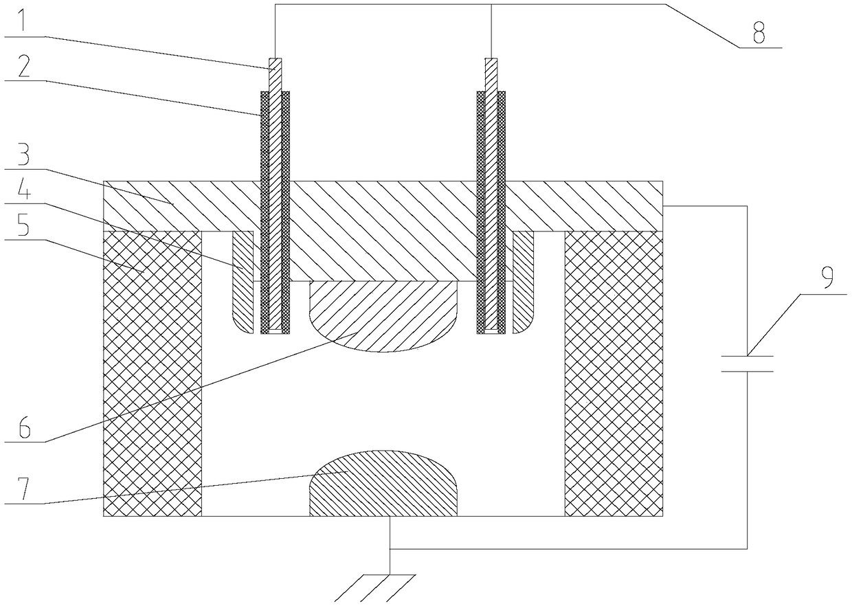
[0036] A dielectric barrier spark pre-ionization discharge electrode, including a discharge anode 7, a discharge cathode 6, an insulating frame 5 and a cathode cover 3, the discharge cathode is located on the cathode cover 3, and the cathode cover outside the discharge cathode is installed There are pre-ionization bar 4 and insulating medium tube 2, spark needle 1 is installed in said insulating medium tube 2, and the tip of spark needle 1 does not touch the bottom of insulating medium tube 2.
[0037] The distance between the tip of the spark needle 1 and the bottom of the insulating medium tube 2 is 0.9mm.
[0038] The discharge cathode 6 is installed in the middle of the cathode cover plate 3, and the side of the discharge cathode 6 opposite to the discharge anode 7 is an arc-shaped protrusion.
[0039] The insulating medium tube 2 is parallel to the pre-ionization strip 4 , and the insulating medium tube 2 and the pre-ionization strip 4 are installed on both sides of the c...
Embodiment 2
[0045] A dielectric barrier spark pre-ionization discharge electrode, comprising a discharge anode 7, a discharge cathode 6, an insulating frame 5, a cathode cover plate 3, a pre-ionization strip 4 and an insulating dielectric tube 2 are installed on the cathode cover plate 3, and the insulating A spark needle 1 is installed in the medium pipe 2, and the tip of the spark needle 1 does not touch the bottom of the insulating medium pipe 2.
[0046] The distance between the tip of the spark needle 1 and the bottom of the insulating medium tube 2 is 1.5mm.
[0047] The discharge cathode 6 is installed in the middle of the cathode cover plate 3, and the side of the discharge cathode 6 opposite to the discharge anode 7 is an arc-shaped protrusion.
[0048] The insulating medium tube 2 is parallel to the pre-ionization strip 4 , and the insulating medium tube 2 and the pre-ionization strip 4 are installed on both sides of the cathode cover plate 3 in parallel. The pre-ionization bar...
Embodiment 3
[0054] A dielectric barrier spark pre-ionization discharge electrode, comprising a discharge anode 7, a discharge cathode 6, an insulating frame 5, a cathode cover plate 3, a pre-ionization strip 4 and an insulating dielectric tube 2 are installed on the cathode cover plate 3, and the insulating A spark needle 1 is installed in the medium pipe 2, and the tip of the spark needle 1 does not touch the bottom of the insulating medium pipe 2.
[0055] The distance between the tip of the spark needle 1 and the bottom of the insulating medium tube 2 is 3.0mm.
[0056] The discharge cathode 6 is installed in the middle of the cathode cover plate 3 , and the discharge cathode 6 has the same shape as the discharge anode 7 .
[0057] The insulating medium tube 2 and the pre-ionization strip 4 are installed side by side on the outside of the cathode cover plate 3 , there are two insulating medium tubes 2 , and the pre-ionization strip 4 is located in the middle of the two insulating mediu...
PUM
 Abstract
Description
Claims
Application Information
PatSnap Eureka turns technology decisions into work you can execute. Powered by our Innovation Knowledge Graph, it runs expert workflows across engineering, life sciences, materials and intellectual property. Get your review-ready output in minutes.


