
Flow control device

A technology of flow control device and drainage groove, which is applied in the direction of valve device, valve operation/release device, valve details, etc., which can solve the problems of large fluid flow, instability, waste, etc., and achieve noise reduction, stable flow, and optimized use environmental effects

Active Publication Date: 2018-12-04
SANHUA AWECO APPLIANCE SYST WUHU CO LTD
View PDF7 Cites 1 Cited by
  • Summary
  • Abstract
  • Description
  • Claims
  • Application Information

AI Technical Summary

Problems solved by technology

The fluid flow rate changes with the change of pressure, which is extremely unstable, and the user experience of the product is not good; at the same time, when the pressure increases, the fluid flow rate will be too large, resulting in waste

Method used


Image

  • Flow control device
  • Flow control device
  • Flow control device

Examples


Embodiment Construction

[0023] In order to make the object, technical solution and advantages of the present invention clearer, the present invention will be described in detail below in conjunction with the accompanying drawings and specific embodiments.

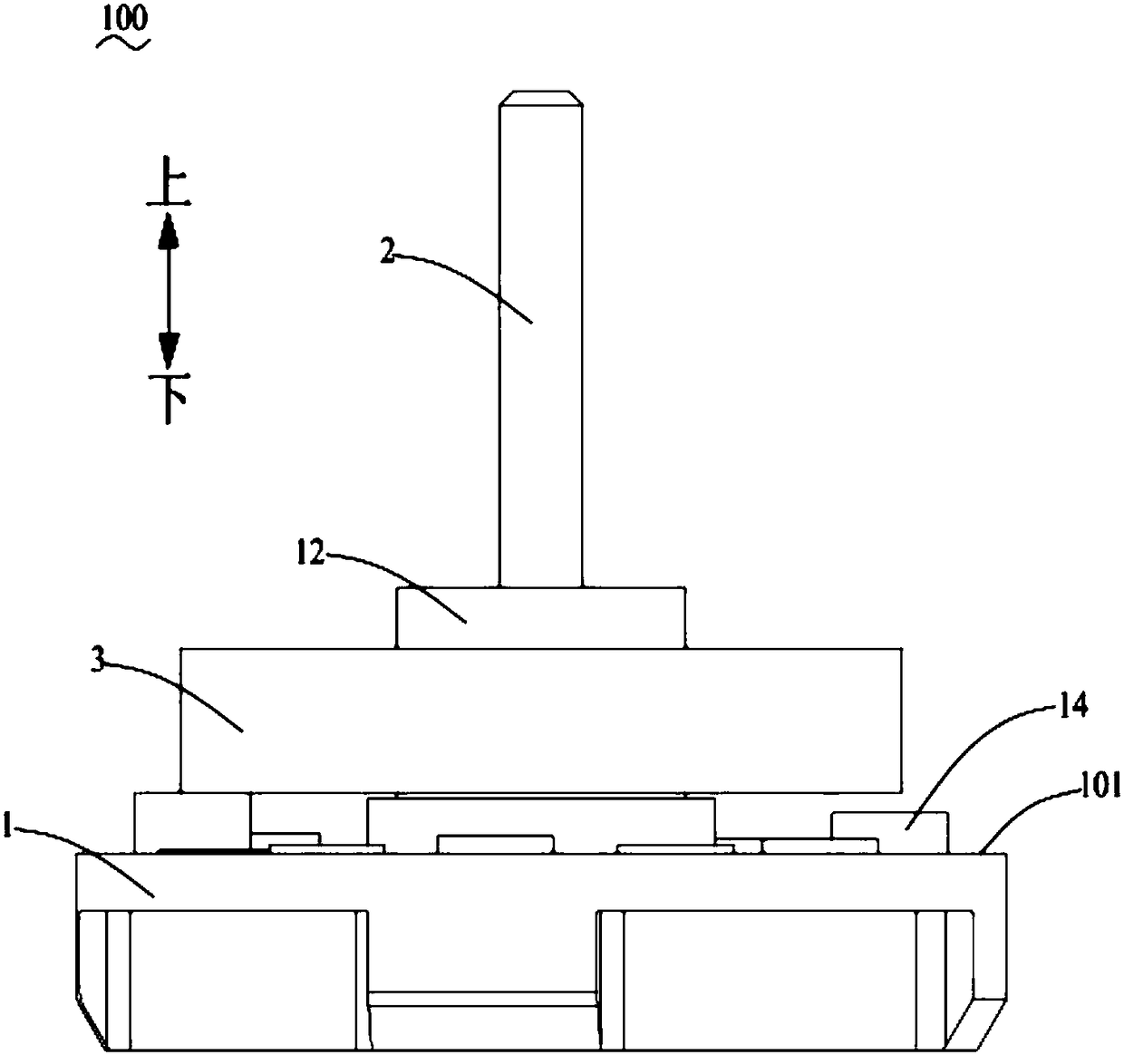
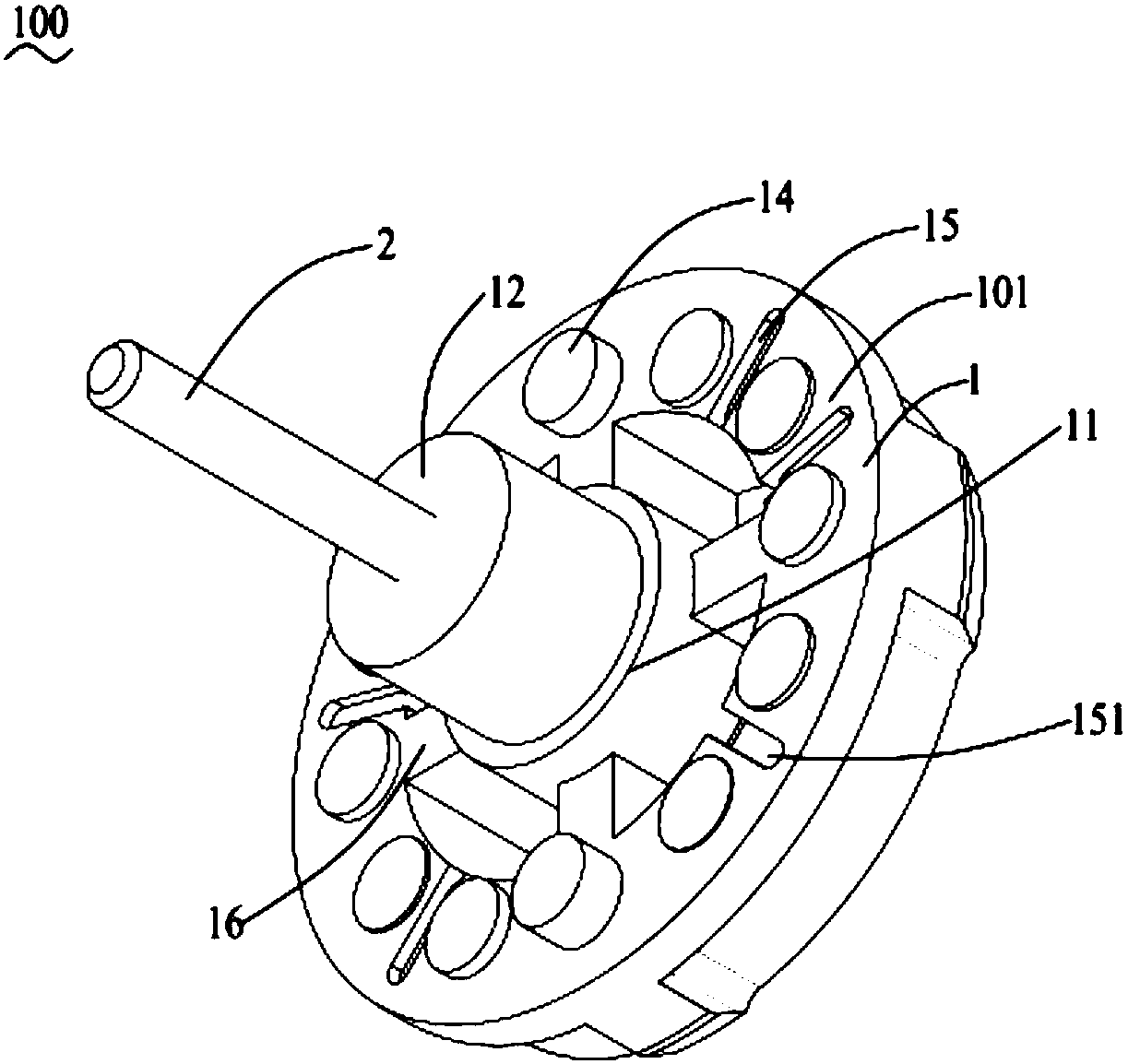
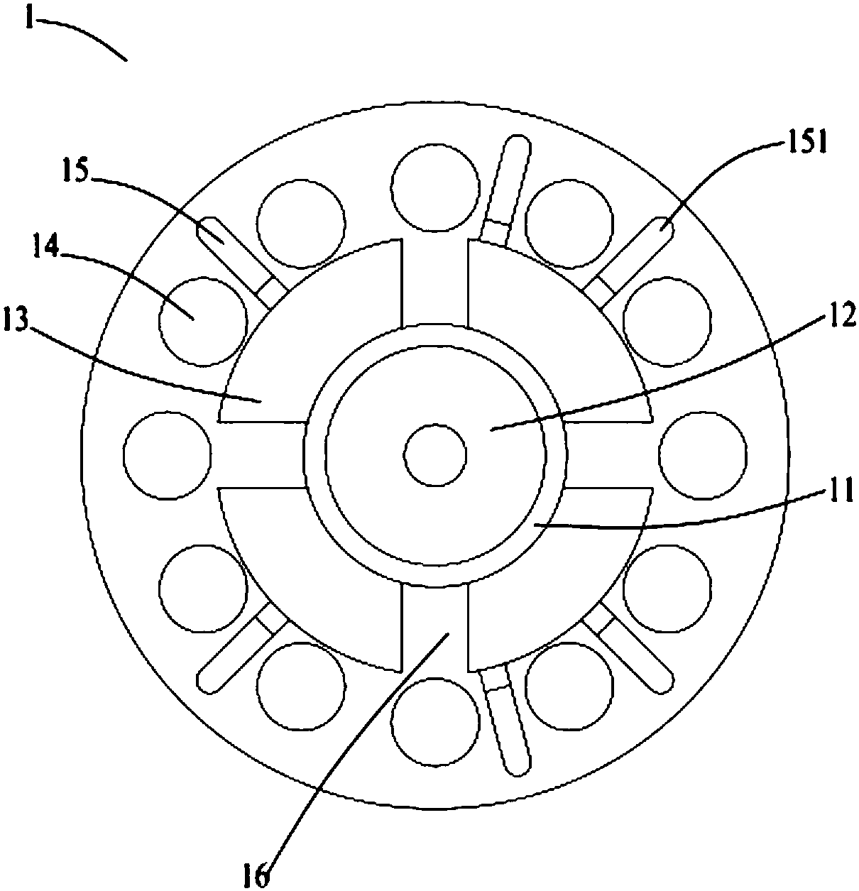
[0024] see Figure 1 to Figure 4 The flow control device 100 shown includes a body part 1, a hub 12 protruding upward from the middle of the body part 1, and a boss 11 annularly surrounding the hub 12, and the hub 12 is covered with An elastic adjusting part 3 is provided.

[0025] The flow control device 100 also includes a mounting rod 2 protruding upward from the upper end surface of the hub 12 . The body part 1 and the installation rod 2 are integrally injection-molded, no need to use other connection accessories, saving costs, and avoiding loose connection during use, which affects the normal use of the flow control device 100 . The installation rod 2 is used for connecting with other devices when the flow control device 100 is installed. ...


PUM


Abstract

The invention provides a flow control device comprising a body part, a shaft bossing extending from the upper surface of the body part in an upward protruding mode, and a boss annularly surrounding the shaft bossing. An elastic adjusting piece is arranged on the shaft bossing in a sleeving mode. The body part is provided with a plurality of through holes penetrating through the body part in the up-down direction, and a plurality of flow guiding troughs sunken downwards from the upper surface of the body part. Each through hole communicates with one or more flow guiding troughs. In this way, the stable flow is provided, noise when a fluid passes through the flow control device is lowered, and the use environment is optimized.

Description

technical field [0001] The invention relates to a control device applied to a fluid channel, in particular to a flow control device capable of providing stable flow. Background technique [0002] With the improvement of people's awareness of limited energy conservation, water conservation is more and more valued by people, so the requirements for the conservation of flow control devices are also getting higher and higher. In the initial use stage of the flow control device, the pressure on the fluid is unstable. When the pressure on the fluid is small, the fluid flow rate is small. When the pressure increases, the pressure on the fluid increases, and the fluid flow rate also increases. The fluid flow varies with the pressure, which is extremely unstable, and the user experience of the product is not good; at the same time, when the pressure increases, the fluid flow will be too large, resulting in waste. [0003] In view of this, it is necessary to design an improved flow c...

Claims


Application Information

Patent Timeline
IPC IPC(8): F16K7/17F16K31/126
CPCF16K7/17F16K31/126
Inventor 潘家宝张自平朱立鹏尹斌
Owner SANHUA AWECO APPLIANCE SYST WUHU CO LTD
Learn More