Detector self-inspection method, device and medium and radiation type inspection system

A technology of inspection system and self-inspection device, which is applied in the field of radiation imaging, and can solve problems such as inability to detect detector failures in time, inaccurate inspection results, etc.

Active Publication Date: 2018-12-04
POWERSCAN COMPANY LIMITED
View PDF9 Cites 4 Cited by
  • Summary
  • Abstract
  • Description
  • Claims
  • Application Information

AI Technical Summary

Problems solved by technology

[0003] The present invention aims to provide a detector self-inspection method, device, medium and radiation-type inspection system to solve the problem that the radiation-type inspection system in the prior art cannot find the detector failure in time during the inspection process, which leads to inaccurate inspection results. technical problem

Method used


Image

  • Detector self-inspection method, device and medium and radiation type inspection system
  • Detector self-inspection method, device and medium and radiation type inspection system
  • Detector self-inspection method, device and medium and radiation type inspection system

Examples


Embodiment 1

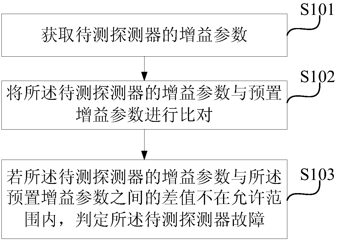
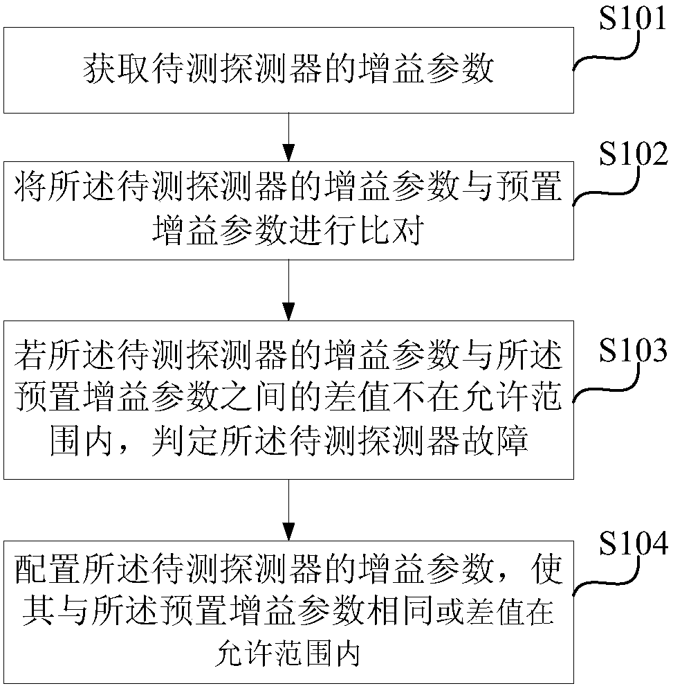
[0081] This embodiment provides a detector self-inspection method, which is applied to the data processing unit of the radiation-type inspection system, and is used for fault detection of the detector in the radiation-type inspection system, such as figure 2 shown, including the following steps:

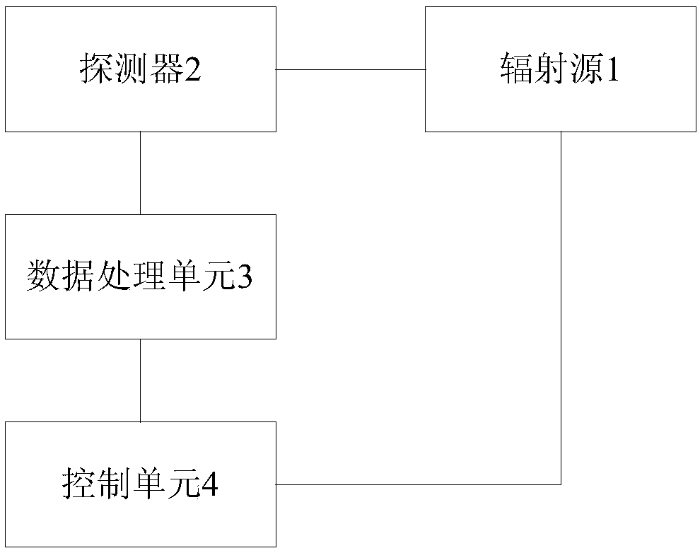
[0082] S101: Obtain a gain parameter of the detector to be tested. Such as figure 1 As shown, the data processing unit 3 is communicatively connected with the detector 2, and it can obtain the detection data of each pixel in the detector 2, and can obtain the gain parameter of each pixel at the same time. The gain parameter of the detector to be tested in this step may be a list or a matrix including the gain parameter of each pixel.

[0083] S102: Compare the gain parameter of the detector to be tested with a preset gain parameter. The preset gain parameter has been pre-stored in the data processing unit 3, and may be a gain parameter written by the user, or a gain parameter cor...

Embodiment 2

[0088] This embodiment provides a detector self-inspection method, which is applied to the data processing unit of the radiation-type inspection system, and is used for fault detection of the detector in the radiation-type inspection system, such as Figure 4 shown, including the following steps:

[0089] S201: Obtain a gain parameter of the detector to be tested.

[0090] S202: Compare the gain parameter of the detector to be tested with a preset gain parameter, if the difference between the gain parameter of the detector to be tested and the preset gain parameter is not within the allowable range, execute step S205 If the difference between the gain parameter of the detector to be tested and the preset gain parameter is within an allowable range, step S203 is executed.

[0091] S203: Obtain the air value of the detector to be tested, and the air value is measured in the following manner: there is no occlusion between the detector to be measured and the radiation source (the...

Embodiment 3

[0109] As another possible solution, such as Figure 6 shown, including the following steps:

[0110] S301: Obtain a gain parameter of the detector to be tested.

[0111] S302: Compare the gain parameter of the detector to be tested with a preset gain parameter, if the difference between the gain parameter of the detector to be tested and the preset gain parameter is not within the allowable range, execute step S306 If the difference between the gain parameter of the detector to be tested and the preset gain parameter is within an allowable range, step S303 is executed.

[0112] S303: Determine the allowable range of the relative standard deviation of the air value of each pixel in the detector to be tested;

[0113] S304: Obtain the air value of the detector to be tested, which includes the air value of each pixel; the air value is measured in the following manner: there is no obstruction (blocking) between the detector to be tested and the radiation source object generall...


PUM


Abstract

The invention provides a detector self-inspection method, device and medium and a radiation type inspection system. In the detection method, obtained gain parameters of a to-be-detected detector are compared with preset gain parameters; if the difference value between the gain parameters of the to-be-detected detector and the preset gain parameters is not in the allowable range, the to-be-detecteddetector is determined to have fault. The preset gain parameters can be gain parameters self-set by a user. Through the scheme, the detector in the radiation inspection system can be automatically detected, so that a relevant responsible person can know the operation status of the detector in real time, and can find out the detector fault in time, so as to avoid the detector fault affecting the accuracy of the inspection result.

Description

technical field [0001] The invention relates to the technical field of radiation imaging, in particular to a detector self-inspection method, device, medium and radiation-type inspection system. Background technique [0002] Since the 1990s, the radial inspection system has become a mature technical means for large-scale container cargo vehicles to be inspected without opening the box. Such as figure 1 As shown, a common radiation inspection system includes a radiation source 1 , a detector 2 including multiple pixels, a data processing unit 3 and a control unit 4 . Under the control of the control unit 4, the radiation source 1 generates a ray beam that penetrates the container, and the pixels in the detector 2 receive the transmitted beam transmitted through the container, and the detector converts the detected transmitted beam into detection data and sends the detection data to To the data processing unit 3, the data processing unit 3 reconstructs the received detection...

Claims


Application Information

Patent Timeline
Patent Type & Authority Applications(China)
IPC IPC(8): G01N23/00
CPCG01N23/00
Inventor 曹艳锋王少锋李苏祺凌敏冯志涛王春雷高正剑
Owner POWERSCAN COMPANY LIMITED
Why Eureka
Try Eureka