Environmental design landscape sample display stand

A display platform and landscape technology, applied in the field of display stands, can solve the problems of not being able to place landscape samples of different sizes, and achieve the effects of simple structure, non-adjustable solution angle, and convenient use

Inactive Publication Date: 2018-12-07
王岚
View PDF7 Cites 4 Cited by
  • Summary
  • Abstract
  • Description
  • Claims
  • Application Information

AI Technical Summary

Problems solved by technology

[0003] Publication No. CN207115838U discloses a display stand for environmental design models. The top center of the display stand body is provided with a mounting hole, and a rotating shaft is fitted in the gap in the mounting hole. A motor driving the rotating shaft is installed in the display stand body. An annular stepped surface is arranged on the outer peripheral wall of the annular stepped surface, and a ring-shaped transparent cover is matched with the gap in the annular groove of the annular stepped surface. A push rod motor and a controller are arranged at the bottom of the display stand body, and the piston of the push rod motor The rod is connected to the bottom of the ring-shaped transparent cover, but the sample displayed on the display table in this patent is a flat display. When the display table is required to display samples tiltedly, this device cannot meet the requirements. At the same time, this device cannot place landscape samples of different sizes, so it is necessary A new type of environmental design landscape sample display stand to meet people's needs

Method used


Image

  • Environmental design landscape sample display stand
  • Environmental design landscape sample display stand
  • Environmental design landscape sample display stand

Examples


Embodiment Construction

[0026] The following will clearly and completely describe the technical solutions in the embodiments of the present invention with reference to the accompanying drawings in the embodiments of the present invention. Obviously, the described embodiments are only some, not all, embodiments of the present invention.

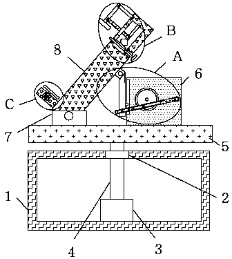
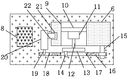
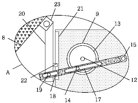
[0027] refer to Figure 1-6 , an environmental design landscape sample display stand, comprising a base 1, the base 1 is a hollow structure, a display stand 5 is movably installed on the top side of the base 1, an adjustment block 6 is fixedly installed on the top side of the display stand 5, and one part of the adjustment block 6 The side is provided with a round hole 9, and a fixed plate 10 is fixedly installed in the round hole 9, and a motor 11 is fixedly installed on one side of the fixed plate 10, and the output shaft of the motor 11 is fixedly installed with a rotating shaft 12 through a first coupling, and the rotating shaft 12 The end away from the motor 11 ...


PUM


Abstract

The invention discloses an environmental design landscape sample display stand. The display stand comprises a base, the base is of a hollow structure, and a display stand body is movably installed atthe top side of the base; an adjustment block is fixedly installed at the top side of the display stand body, a circular hole is formed in one side of the adjustment block, and a fixing plate is fixedly installed in the circular hole; a motor is fixedly installed at one side of the fixing plate; a rotation shaft is fixedly installed on an output shaft of the motor through a first shaft coupler, the end, away from the motor, of the rotation shaft extends out of the circular hole and is fixedly provided with a rotation disc, and a first circular column is fixedly installed at the side, away fromthe rotation shaft, of the rotation disc. The landscape sample display stand is simple in structure, the adjustment rod moves up and down to drive the display stand body to move, and the problem is effectively solved that the angle of the display stand body cannot be adjusted; an L-shaped rotation rod rotates to drive a second connection rod to move, the second connection rod moves to drive a first extrusion plate to move, and the problem is effectively solved that landscape samples different in size cannot be placed. The display stand is convenient to use.

Description

technical field [0001] The invention relates to the technical field of display stands, in particular to an environmental design landscape sample display stand. Background technique [0002] The display stand is also called the physical display stand. When it is connected to a projector and a TV, it can clearly display materials, handouts, objects, slides, etc. It is one of the indispensable teaching equipment for multimedia classrooms. [0003] Publication No. CN207115838U discloses a display stand for environmental design models. The top center of the display stand body is provided with a mounting hole, and a rotating shaft is fitted in the gap in the mounting hole. A motor driving the rotating shaft is installed in the display stand body. An annular stepped surface is arranged on the outer peripheral wall of the annular stepped surface, and a ring-shaped transparent cover is matched with the gap in the annular groove of the annular stepped surface. A push rod motor and a c...

Claims


Application Information

Patent Timeline
IPC IPC(8): A47F5/10
CPCA47F5/10
Inventor 王岚金颂文邹佰晶
Owner 王岚
Why Eureka
Try Eureka