Assembly structure for dust collector and dust collector

An assembly structure and vacuum cleaner technology, applied in vacuum cleaners, applications, household appliances, etc., can solve the problems of complex disassembly and assembly procedures, and achieve the effects of improving user experience, simplifying disassembly and installation procedures, and convenient operation

Pending Publication Date: 2018-12-07
GREE ELECTRIC APPLIANCES INC OF ZHUHAI
View PDF0 Cites 0 Cited by
  • Summary
  • Abstract
  • Description
  • Claims
  • Application Information

AI Technical Summary

Problems solved by technology

[0004] Therefore, the technical problem to be solved by the present invention is to overcome the problem that the disassembly and assembly procedures of the dust cup of the vacuum cleaner in the prior art are too complicated, and to provide an assembly for the vacuum cleaner that can simplify the assembly and disassembly of the dust cup. structure
[0005] Another technical problem to be solved by the present invention is to overcome the problem that the disassembly and assembly procedure of the dust cup of the vacuum cleaner in the prior art is too complicated, and then provide a vacuum cleaner with a simpler dust cup assembly and disassembly procedure

Method used


Image

  • Assembly structure for dust collector and dust collector
  • Assembly structure for dust collector and dust collector
  • Assembly structure for dust collector and dust collector

Examples


Embodiment 1

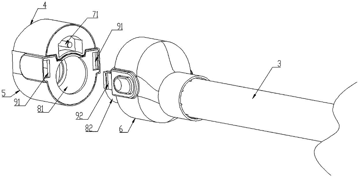
[0049] Such as Figure 1 to Figure 4 As shown, it is Embodiment 1 of the present invention. This embodiment provides an assembly structure applied to a vacuum cleaner. As described in the background technology, the dust cup 2 of the vacuum cleaner in the prior art is disassembled and installed. Too complicated, the assembly structure provided by this embodiment can effectively solve the above problems and simplify the disassembly and installation procedures of the dust cup 2 .

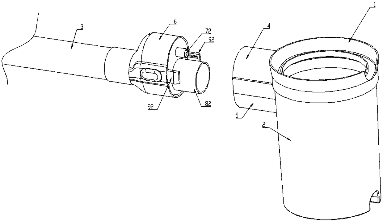
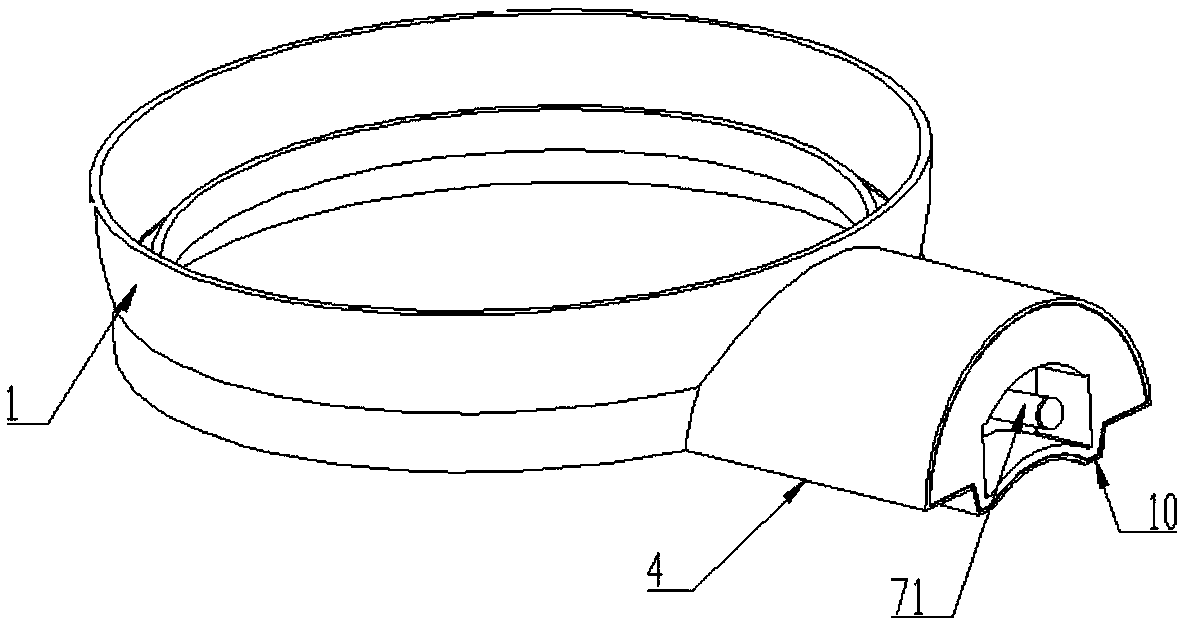
[0050] This embodiment includes an upper joint 4, a lower joint 5 and a pipe joint 6, the upper joint 4 is arranged on the separation device 1 of the vacuum cleaner; the lower joint 5 is arranged on the dust cup 2 of the vacuum cleaner; the pipe joint 6 is arranged on the air inlet pipe 3 of the vacuum cleaner One end where the upper airflow flows out; the upper joint 4 and the lower joint 5 are detachably connected to the pipe joint 6 at the same time, and can keep the relative position unchanged unde...

Embodiment 2

[0061] This embodiment is a vacuum cleaner, which includes an air inlet pipe 3, a dust cup 2 and a separation device 1. The separation device 1 is installed in the shape of a cover at the mouth of the dust cup 2, and the side wall of the dust cup 2 communicates with the air inlet pipe 3. . The dust cup 2, the air inlet pipe 3 and the separation device 1 are installed together through the assembly structure in the first embodiment.

[0062] Since this embodiment includes the assembly structure in embodiment 1, it also has all the technical effects brought by the assembly structure in embodiment 1.


PUM


Abstract

The invention discloses an assembly structure for a dust collector and the dust collector, and belongs to the technical field of dust collectors. The assembly structure comprises an upper connector arranged on a separation device of the dust collector, a lower connector arranged on a dust cup of the dust collector, and a pipe joint arranged at the end, for air to flow out, of an air inlet pipe ofthe dust collector, wherein the upper connector and the lower connector can be detachably connected to the pipe joint at the same time and keep the relative position unchanged under the limitation ofthe pipe joint. By means of the assembly structure, the detaching and installing process of the dust cup can be simplified, a user can more conveniently detach the dust cup, the assembly structure hasthe advantages of being convenient to operate, high in sealing force, smooth in surface and the like, and the effects of improving the dust-air separation efficiency and improving the dust accumulation capacity of the dust cup can be achieved.

Description

technical field [0001] The invention relates to the technical field of vacuum cleaners, in particular to an assembly structure applied to vacuum cleaners and the vacuum cleaner. Background technique [0002] The dust cup of the known vacuum cleaner is generally installed on the separation device, and the separation device is generally used to install a filter device and a negative pressure generating device (such as a turbofan, a blower fan, etc.), and the separation device is generally made as a cover for the dust cup, and the cover is mounted on the dust cup. The mouth of the cup; the side wall of the dust cup is generally provided with an air inlet, and the air inlet is connected with the air inlet pipe through a pipe joint. [0003] The separation device and the dust cup in the prior art are generally connected by a set of buckles, or the separation device and the dust cup are connected by threads; and the dust cup and the air inlet are plugged or snapped by a pipe joint...

Claims


Application Information

Patent Timeline
IPC IPC(8): A47L9/00
CPCA47L9/00
Inventor 陈勇王德旭廖泓斌陈闪毅黄月林任敏李吉孟得浩
Owner GREE ELECTRIC APPLIANCES INC OF ZHUHAI
Why Eureka
Try Eureka