Magnetic separation device with uniform diluting feeding function

A magnetic separation device and material feeding technology, which is applied in the field of magnetic separation, can solve problems such as not being able to adapt to assembly line production, and achieve high efficiency

Active Publication Date: 2018-12-07
FOSHAN CHENG XIAN TECH CO LTD +1
View PDF11 Cites 1 Cited by
  • Summary
  • Abstract
  • Description
  • Claims
  • Application Information

AI Technical Summary

Problems solved by technology

The existing magnetic separation device can't evenly spread the feed material, and can't adapt to the production of the assembly line

Method used


Image

  • Magnetic separation device with uniform diluting feeding function
  • Magnetic separation device with uniform diluting feeding function
  • Magnetic separation device with uniform diluting feeding function

Examples


Embodiment Construction

[0019] The following will clearly and completely describe the technical solutions in the embodiments of the present invention with reference to the accompanying drawings in the embodiments of the present invention. Obviously, the described embodiments are only some, not all, embodiments of the present invention.

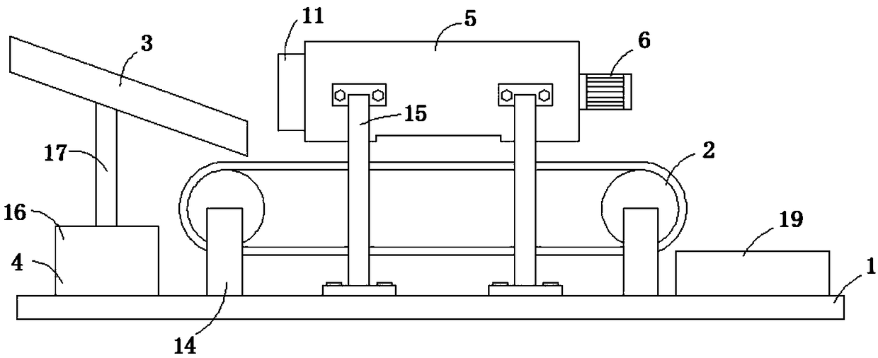
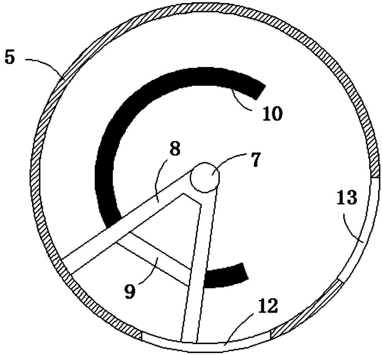
[0020] refer to Figure 1-4 , a magnetic separation device with a function of evenly diluting feeding, comprising a base plate 1, a belt conveyor 2 is provided on the upper side of the base plate 1, and a storage box 19 is provided on the side of the belt conveyor 2 away from the feeding rail 3, and the belt The end of the conveyor 2 away from the feeding rail 3 extends to the upper side of the storage box 19, and the ore that has been magnetically separated can be stored. The belt conveyor 2 is fixedly connected to the bottom plate 1 through a plurality of first fixing rods 14. The belt conveyor 2. The feeding rail 3 is provided on the left side, and the feeding rai...


PUM


Abstract

The invention discloses a magnetic separation device with a uniform diluting feeding function. The magnetic separation device comprises a bottom plate. A belt conveyor is arranged on the upper side ofthe bottom plate; the belt conveyor is fixedly connected to the bottom plate through a plurality of first fixed bars; a feeding rail is fixedly connected to the upper end surface of the bottom platethrough a vibrating mechanism; a rotary drum is fixedly connected to the upper end surface of base through a plurality of second fixed bars; one end of the rotary drum is fixedly connected to a motor;a rotary shaft is horizontally arranged in the rotary drum; a groove is formed in the end, far away from the rotary shaft, of a rotating block; an electromagnet is fixedly connected in the groove; apower supply is electrically connected to an arc-shaped conductive block; one end of the electromagnet is in contact with the arc-shaped conductive block; a magnetic separation port is formed in the lower end wall of the rotary drum; a discharge port is formed in the side wall of the rotary drum; and the discharge port corresponds to the arc-shaped conductive block in position.

Description

technical field [0001] The invention relates to the technical field of magnetic separation, in particular to a magnetic separation device with the function of uniformly diluted feeding. Background technique [0002] Magnetic separation belongs to the selection of ilmenite. It uses the difference in magnetic permeability of various minerals to make them pass through a magnetic field. Because different minerals have different responses to the magnetic field, the minerals with high magnetic permeability are sucked up by the disk, and then fall off when they lose their magnetism. When it is collected, those with low magnetic permeability will not be sucked up, and will be left in the material or taken out as tailings with the rotating belt to be separated. The existing magnetic separation device cannot evenly spread the feed material, and cannot adapt to the production of the assembly line. [0003] For this reason, we propose a magnetic separation device with the function of ...

Claims


Application Information

Patent Timeline
Patent Type & Authority Applications(China)
IPC IPC(8): B03C1/18
CPCB03C1/18
Inventor 龙克文颜天宝杜海枝
Owner FOSHAN CHENG XIAN TECH CO LTD
Why Eureka
Try Eureka