
Machined product positioning device

A positioning device and machining technology, used in positioning devices, metal processing equipment, metal processing mechanical parts, etc., can solve problems such as difficulty in ensuring product positioning accuracy, inability to meet product high-precision positioning requirements, and large cumulative tolerances. Guarantee high-precision positioning requirements, simple structure, high positioning accuracy

Active Publication Date: 2020-09-25
GEER TECH CO LTD
View PDF10 Cites 0 Cited by
  • Summary
  • Abstract
  • Description
  • Claims
  • Application Information

AI Technical Summary

Problems solved by technology

However, for products with processed end faces, the positioning holes and bearing surfaces are all on the side, so it is impossible to mount the machine, and it is difficult to ensure the positioning accuracy of the final product
At present, the fixing of products with processed end faces is purely assembled by positioning holes of tooling parts to ensure assembly tolerances. However, this method has a large cumulative tolerance and cannot meet the high-precision positioning requirements of products.

Method used


Image

  • Machined product positioning device
  • Machined product positioning device
  • Machined product positioning device

Examples


Embodiment Construction

[0023] Below in conjunction with accompanying drawing and embodiment, further elaborate the present invention.

[0024] The orientations involved in this specification are all subject to the orientations shown in the drawings, which only represent relative positional relationships, not absolute positional relationships.

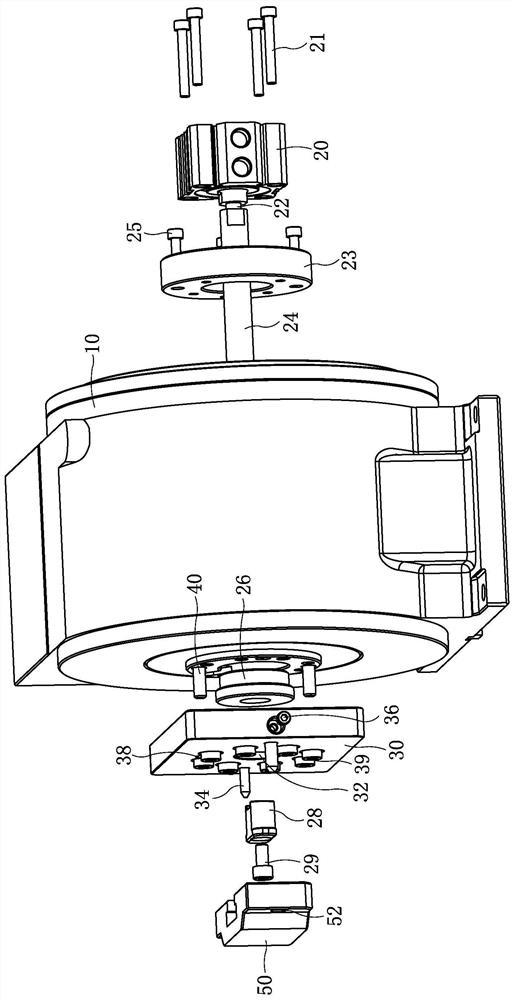
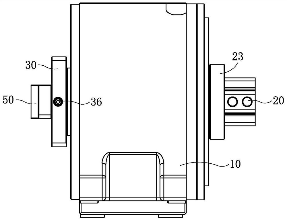
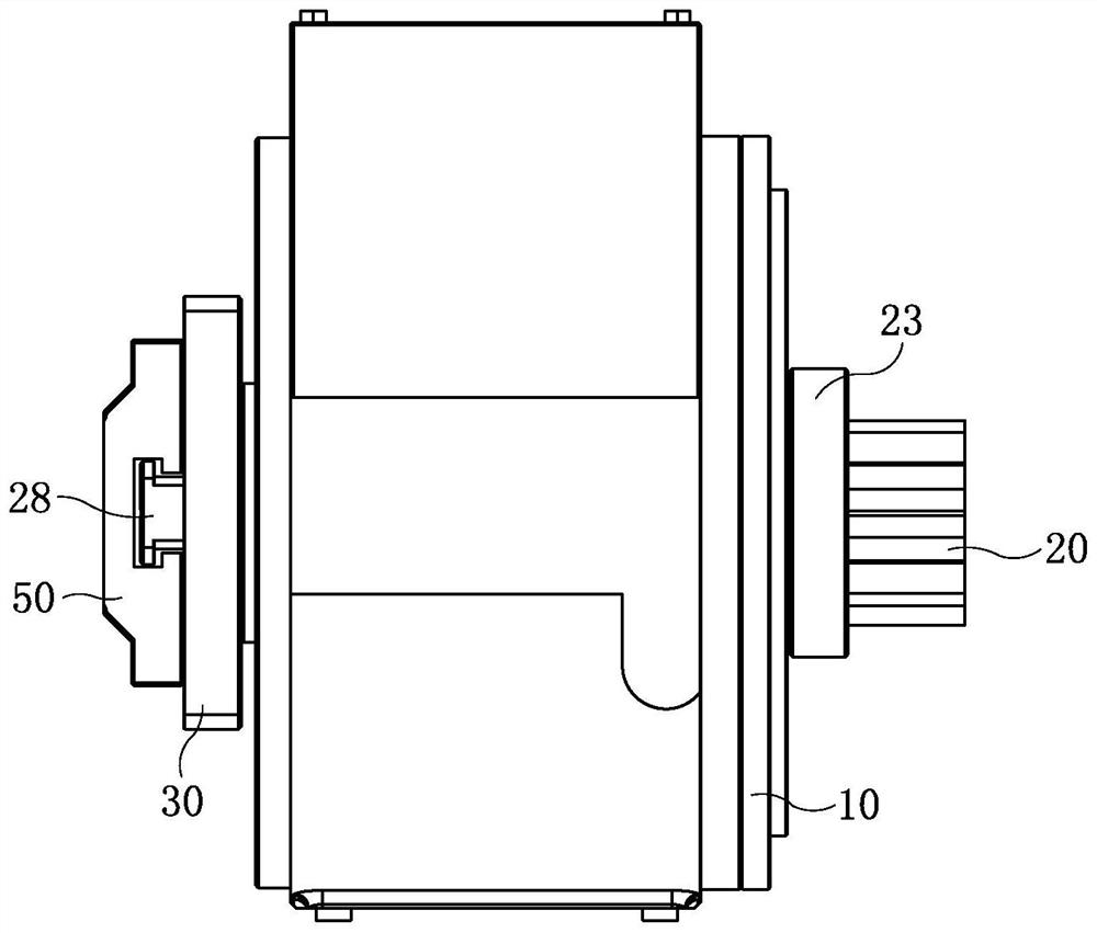
[0025] Such as figure 1 and figure 2 As shown together, a machined product positioning device includes a motion mechanism for driving the product 50 to move. In CNC machine tool processing, the motion mechanism usually refers to a three-axis mechanism or a four-axis mechanism, and the three-axis mechanism can drive the product on the X axis. , Y-axis, and Z-axis move in three directions. The four-axis mechanism is based on the three-axis mechanism and an X-axis rotation is added. In this embodiment, the motion mechanism is preferably the four-axis mechanism 10. One side of the four-axis mechanism 10 is fixed with a tooling plate 30 for positioning the prod...


PUM


Abstract

The invention discloses a machined product positioning device and relates to the technical field of metal machining equipment. The machined product positioning device comprises a moving mechanism fordriving a product to move, a tool plate for positioning the product is fixed to one side of the moving mechanism, and a via hole is formed in a position, corresponding to a center hole of the moving mechanism, of the tool plate; an air cylinder is fixed to the other side of the moving mechanism, a piston rod of the air cylinder is connected to a pull rod, and the pull rod successively penetrates the center hole of the moving mechanism and the via hole and is provided with a product positioning pressing head capable of pushing the product away from or pulling the product close to the tool platealong with action of the air cylinder. The machined product positioning device disclosed by the invention solves the technical problem that the machined product in the prior art is low in positioningprecision. The machined product positioning device disclosed by the invention can meet the high precision positioning demand of the product, and is simple in structure, low in cost and convenient toarrange.

Description

technical field [0001] The invention relates to the technical field of metal processing equipment, in particular to a positioning device for end surface processed products. Background technique [0002] In the field of metal CNC (numerical control machine tool) precision machining, in order to ensure the machining accuracy of products, tooling is required to clamp and fix products. After the machining is completed, the CNC machine tool performs precision correction according to its own coordinates, so as to ensure the positioning accuracy of the tooling to the product to the greatest extent. This method can reduce the difficulty of erection, improve the efficiency of erection, and reduce the accuracy requirements of tooling assembly. However, for products with processed end faces, the positioning holes and bearing surfaces are all on the side, so it cannot be machined, and it is difficult to ensure the positioning accuracy of the final product. At present, the fixing of pr...

Claims


Application Information

Patent Timeline
Patent Type & Authority Patents(China)
IPC IPC(8): B23Q3/08
CPCB23Q3/08
Inventor 程宝高统帅唐思敏
Owner GEER TECH CO LTD
Learn More