
Mold table facilitating height adjusting and used for mold production

A technology for adjusting height and mold table, applied in the direction of manufacturing tools, grinding machine parts, and fixing grinding wheel devices, etc., can solve the problems of reducing efficiency, troublesome and cumbersome mold replacement, increasing manpower input, etc., to reduce pressure. , convenient clamping, reducing the effect of rigid contact force

Inactive Publication Date: 2018-12-07
苏州琦少工程科技有限公司
View PDF7 Cites 3 Cited by
  • Summary
  • Abstract
  • Description
  • Claims
  • Application Information

AI Technical Summary

Problems solved by technology

The original mold is a single individual mold, which needs to be replaced continuously during use, but in the process of replacement, the replacement of the mold is often quite troublesome and cumbersome, which greatly increases the input of manpower , reducing the efficiency
[0003] In the mold production work, it is often necessary to use the mold platform. The staff can operate various molds to clamp and process the parts on the platform. In the processing operation, due to the different sizes of the parts, the processing process is different. Operators There are also differences in the height of the same mold table. These factors will cause the height of the same mold table to not be suitable for all processing operations. Now a mold table device that can flexibly adjust the height is needed to meet the requirements for the height adjustment of the mold table in machining. , so that the mold table can be used in a wider range

Method used


Image

  • Mold table facilitating height adjusting and used for mold production
  • Mold table facilitating height adjusting and used for mold production
  • Mold table facilitating height adjusting and used for mold production

Examples


Embodiment Construction

[0026] The following will clearly and completely describe the technical solutions in the embodiments of the present invention with reference to the accompanying drawings in the embodiments of the present invention. Obviously, the described embodiments are only some, not all, embodiments of the present invention.

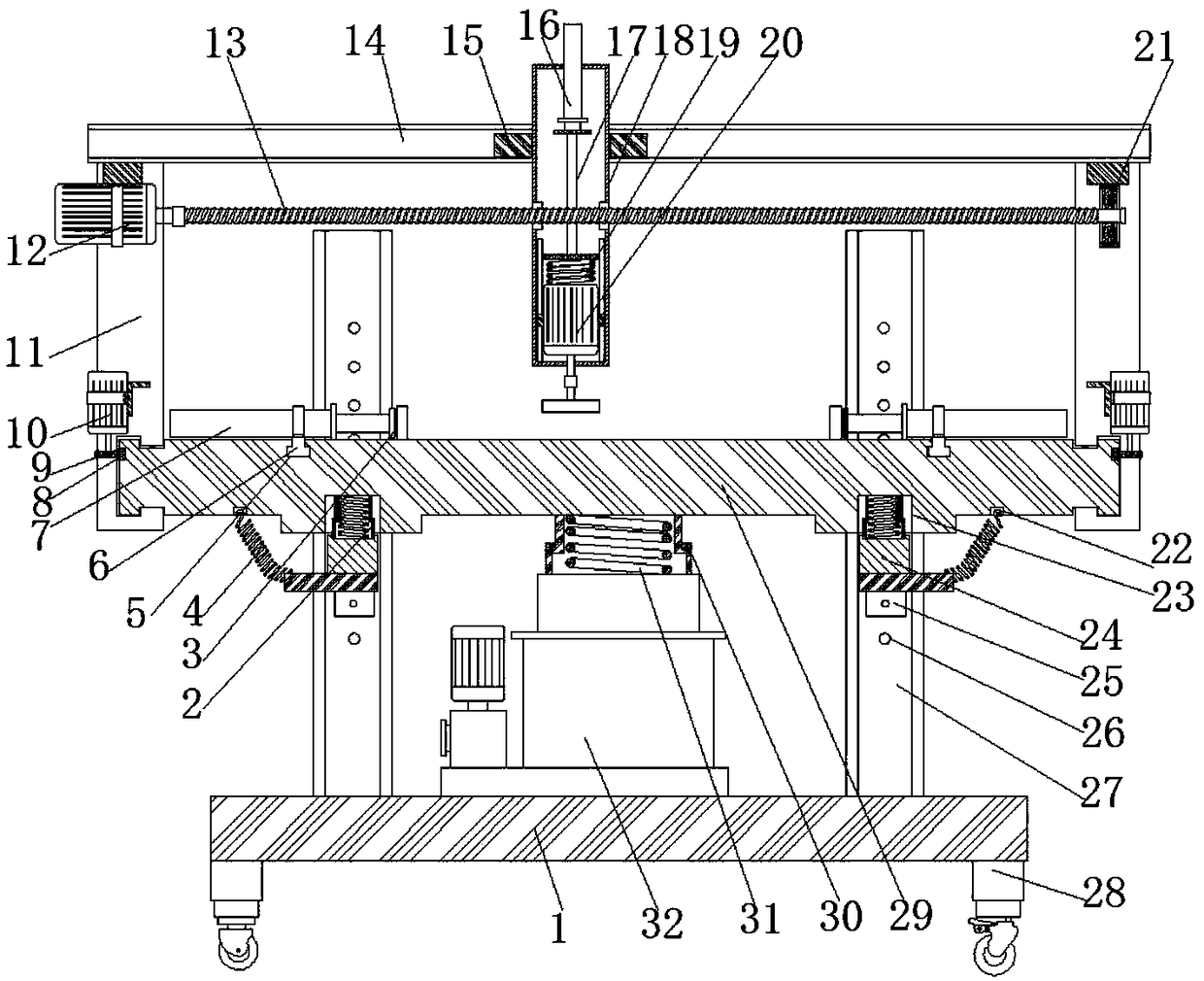
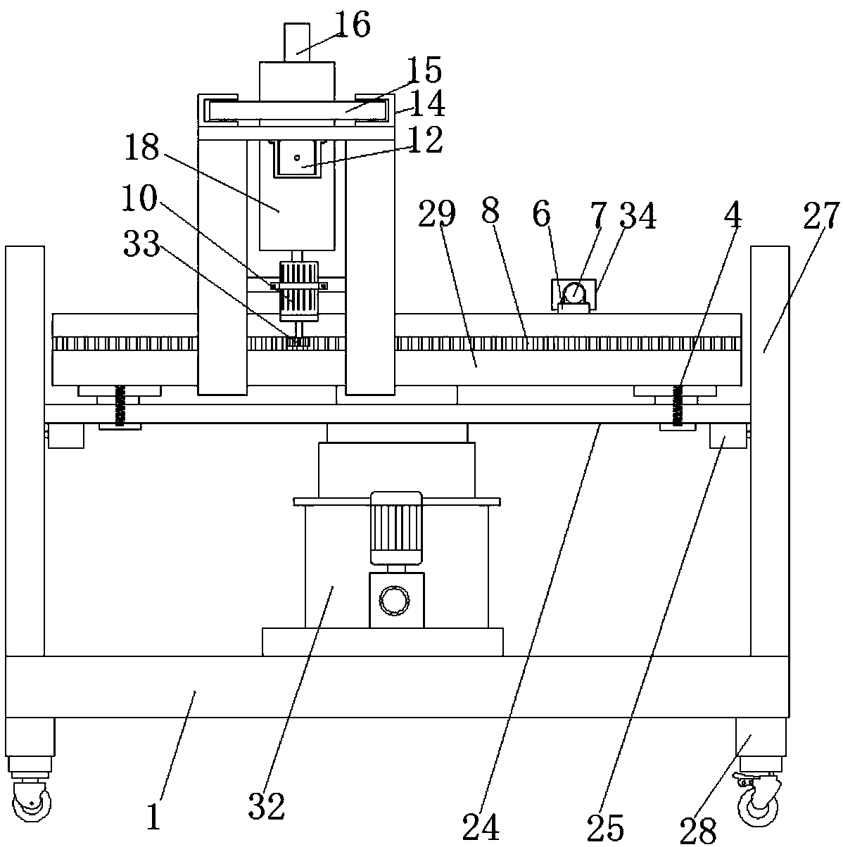
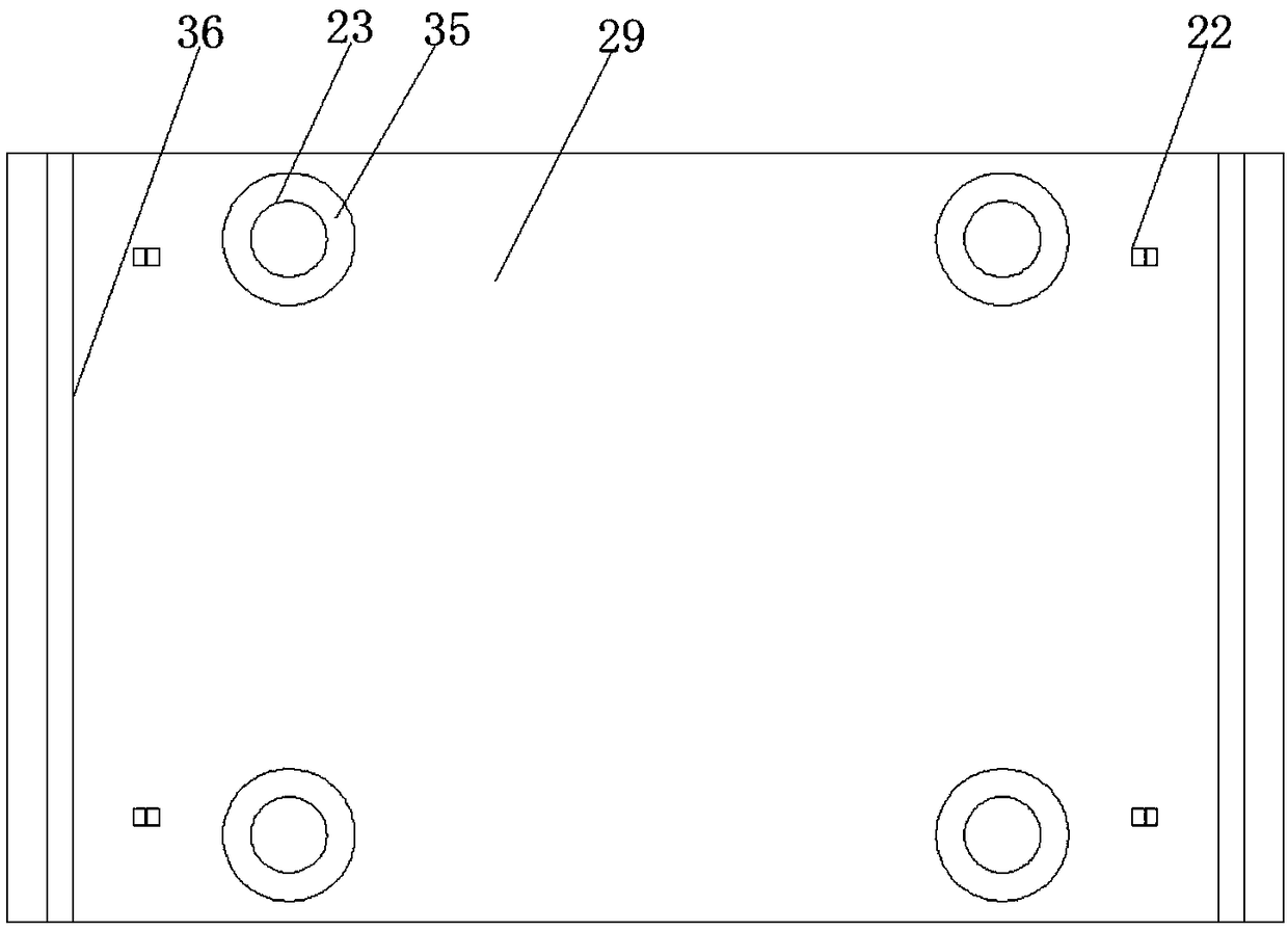
[0027] refer to Figure 1-5 , a mold table that is convenient for height adjustment for mold production, including a base 1, four channel steel columns 27 are welded on the upper surface of the base 1 near both sides, and the openings of the four channel steel columns 27 are opposite to each other, and the channel steel columns 27 There are limit holes 26 equidistantly distributed at the bottom of the bottom, and the same square rod 24 is slidably connected between the two channel steel columns 27 opposite to the opening, and the lower surface of the square rod 24 is fixed by screws near the edges of both ends. The electric control positioning pin 25, and the shaft d...


PUM


Abstract

The invention belongs to the technical field of mold tables, and particularly relates to a mold table facilitating height adjusting and used for mold production. The problem that the height of the mold table cannot well adapt to all machining operations is solved. The mold table comprises a base, four box iron stand columns are welded to the positions, close to the two sides, of the upper surfaceof the base, every two openings of the four box iron stand columns are opposite, limiting holes distributed at equal distances are formed in the bottoms of the box iron stand columns, the same squarerod is in sliding connection between two box iron stand columns with opposite openings, electric control positioning pins are fixed to the positions, close to two end edges, of the lower surfaces of the square rods through screws, the diameter of a shaft rod of each electric control positioning pin is matched with the size of the limiting holes, and a hydraulic cylinder is fixed to the middle of the upper surface of the base through a bolt. When height does not need to be adjusted for a long time, the height is stabilized to the limiting holes on the same horizontal plane, the pressure of a worktable to the hydraulic cylinder on the bottom is reduced, and it is ensured that a worktable cannot descend.

Description

technical field [0001] The invention relates to the technical field of mold tables, in particular to a mold table for easy height adjustment for mold production. Background technique [0002] With the continuous development of modern industry, the use of integrated molds is also constantly updated. The original mold is a single individual mold, which needs to be replaced continuously during use, but in the process of replacement, the replacement of the mold is often quite troublesome and cumbersome, which greatly increases the input of manpower , reducing the efficiency. [0003] In the mold production work, it is often necessary to use the mold platform. The staff can operate various molds to clamp and process the parts on the platform. In the processing operation, due to the different sizes of the parts, the processing process is different. Operators There are also differences in the height of the same mold table. These factors will cause the height of the same mold tabl...

Claims


Application Information

Patent Timeline
IPC IPC(8): B24B41/06B24B27/00B24B47/04B24B41/02B24B41/00B24B55/00B24B45/00
CPCB24B41/06B24B27/0007B24B27/0015B24B41/00B24B41/007B24B41/02B24B45/003B24B47/04B24B55/00
Inventor 刘会
Owner 苏州琦少工程科技有限公司
Learn More