Energy-saving type plastic pipe cutting and polishing device

A technology for cutting and grinding plastic pipes, which is applied in the direction of grinding machines, grinding workpiece supports, grinding/polishing equipment, etc., can solve problems such as unsatisfactory fixing effects, achieve good fixing effects, avoid economic losses, and reduce the size of the working space Effect

Active Publication Date: 2018-12-07
宿迁市名扬建设工程有限公司
View PDF5 Cites 15 Cited by
  • Summary
  • Abstract
  • Description
  • Claims
  • Application Information

AI Technical Summary

Problems solved by technology

[0004] The purpose of the present invention is to provide an energy-saving plastic pipe cutting and grinding device, which has the advantage of good fixing effect and solves the problem of unsatisfactory fixing effect of common energy-saving plastic pipe cutting and grinding devices

Method used


Image

  • Energy-saving type plastic pipe cutting and polishing device
  • Energy-saving type plastic pipe cutting and polishing device

Examples


no. 1 approach

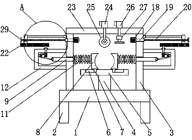
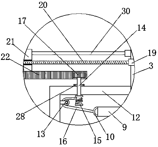
[0017] First implementation: see Figure 1-2 , an energy-saving plastic pipe cutting and polishing device, comprising a bottom plate 1, the left and right sides of the bottom of the bottom plate 1 are fixedly connected with support seats 2, the left and right sides of the top of the bottom plate 1 are fixedly connected with side plates 3, and the middle of the top of the bottom plate 1 The point is fixedly connected with a support block 4, and the top of the support block 4 is fixedly connected with a fixed plate 5, and the top of the fixed plate 5 is symmetrically provided with two chute 6, and the inside of the chute 6 is movably connected with a slider 7, and the slider 7 The top of the top passes through the chute 6 and extends to the outside to be fixedly connected with an arc splint 8, and the opposite sides of the two arc splints 8 are fixedly connected with a fixing rod 9, and the end of the fixing rod 9 away from the arc splint 8 runs through the side plate 3 and exte...

no. 2 approach

[0020]The second embodiment: an energy-saving plastic pipe cutting and polishing device, including a bottom plate 1, the left and right sides of the bottom of the bottom plate 1 are fixedly connected with support seats 2, and the left and right sides of the top of the bottom plate 1 are fixedly connected with side plate 3, a support block 4 is fixedly connected to the midpoint of the top of the base plate 1, and a fixed plate 5 is fixedly connected to the top of the support block 4, and two slide grooves 6 are symmetrically opened on the top of the fixed plate 5, so that The inside of the chute 6 is movably connected with a slider 7, and the top of the slider 7 runs through the chute 6 and extends to the outside thereof to be fixedly connected with an arc-shaped splint 8, and the opposite sides of the two arc-shaped splints 8 are fixedly connected. There is a fixed rod 9, and the end of the fixed rod 9 away from the arc-shaped splint 8 runs through the side plate 3 and extends ...


PUM


Abstract

The invention discloses an energy-saving type plastic pipe cutting and polishing device comprising a base plate. The left side and the right side of the bottom of the base plate are both fixedly connected with supporting seats. The left side and the right side of the top of the base plate are both fixedly connected with side plates. A supporting block is fixedly connected with the center point ofthe top of the base plate. A fixing plate is fixedly connected with the top of the supporting block. The top of the fixing plate is symmetrically provided with two sliding grooves. According to the energy-saving type plastic pipe cutting and polishing device, through mutual operation of the sliding grooves, arc clamping plates, fixing rods, reset springs, protective covers, pulleys, rotating shafts, coiling drums, steel wire ropes, gears, forward and reverse motors, forward and reverse rotating shafts, threaded rods, threaded sleeves and racks, the plastic pipe cutting and polishing device achieves a good fixing effect and can stably fix the plastic pipes of different diameters, the situation that in the cutting process, since the plastic pipe deflects, the plastic pipe is damaged is avoided, unnecessary economic loss is avoided, and the production cost is reduced for a factory.

Description

technical field [0001] The invention relates to the technical field of plastic pipes, in particular to an energy-saving plastic pipe cutting and grinding device. Background technique [0002] Plastic pipes are generally made of synthetic resin, that is, polyester, added with stabilizers, lubricants, plasticizers, etc., and extruded in a pipe making machine by the "plastic" method. It is mainly used for water supply system piping, drainage, exhaust and sewage sanitary pipes, underground drainage pipe systems, rainwater pipes, and threading pipes for wire installation in housing construction. [0003] The common energy-saving plastic pipe cutting and grinding device has an unsatisfactory fixing effect, and cannot stably fix plastic pipes of different diameters, which will easily lead to deflection of the plastic pipe during the cutting process of the plastic pipe, resulting in plastic pipe The damage to the manufacturer brings considerable economic losses and increases the pr...

Claims


Application Information

Patent Timeline
Patent Type & Authority Applications(China)
IPC IPC(8): B26D7/02B24B5/36B24B41/06
CPCB24B5/36B24B41/06B26D7/02B26D2007/013
Inventor 金世杰
Owner 宿迁市名扬建设工程有限公司
Why Eureka
Try Eureka