template divider

A dividing machine and template technology, applied in plastic recycling, recycling technology and other directions, can solve the problems of different sizes of template fragments and increased melting time of template fragments, so as to achieve basically the same melting speed, increase melting time, and save energy. Effect

Active Publication Date: 2020-09-01
HEBEI COLLEGE OF IND & TECH
View PDF3 Cites 0 Cited by
  • Summary
  • Abstract
  • Description
  • Claims
  • Application Information

AI Technical Summary

Problems solved by technology

[0004] The object of the present invention is to provide a template splitting machine, aiming to solve the problem that after the plastic template is broken, the size of the template fragments is different, resulting in an increase in the melting time of the template fragments

Method used


Image

  • template divider
  • template divider
  • template divider

Examples


specific Embodiment approach

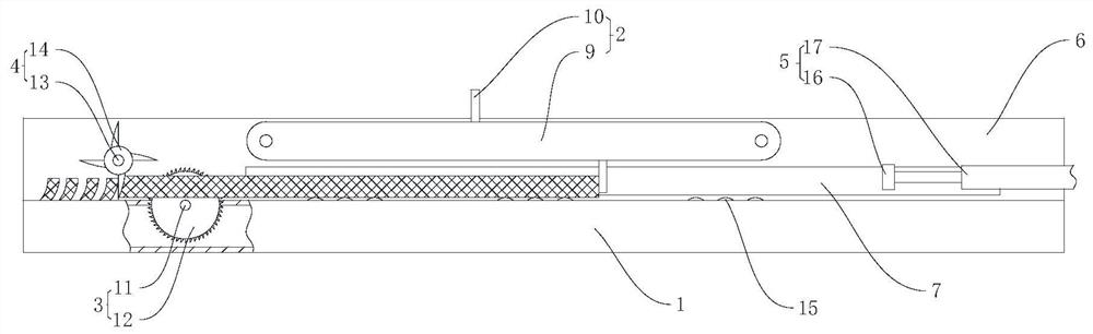
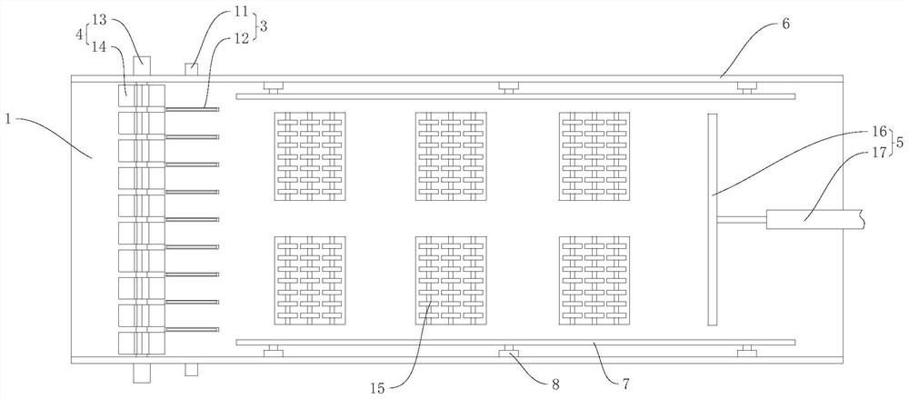
[0029] Furthermore, please also refer to figure 1 and figure 2 , as a specific embodiment of the template dividing machine provided by the present invention, the push plate assembly 5 includes a push plate 16 for pushing the template to the bottom of the drive assembly 2 and a cylinder 17 that drives the push plate 16 to move, and the cylinder 17 is arranged horizontally. The right end of the cylinder 17 is the cylinder body, and the left end is the ejector rod. The cylinder body is fixed on the right end of the workbench 1, and the cylinder body can also be fixed separately. It is necessary to ensure that the cylinder 17 is stable, and the left end of the ejector rod is welded and fixed vertically to the push plate 16. Can be one, also can be a plurality of air cylinders 17 of synchronous operation, when a plurality of air cylinders 17 are set, must guarantee the synchronous operation of air cylinder 17, air cylinder 17 also can be hydraulic cylinder, electric push rod etc.,...


PUM


Abstract

The invention provides a formwork slicing machine, and belongs to the technical field of crushing equipment. The formwork slicing machine comprises a workbench, a driving assembly arranged above the workbench, a slicing assembly arranged at the left end of the workbench and a cutting-off assembly arranged at the left end of the workbench. The cutting-off assembly is located on the left side of theslicing assembly. According to the formwork slicing machine provided by the invention, formworks are placed on a horizontal working face at the upper end of the workbench, and the driving assembly isfixedly arranged above the workbench and used for driving the formworks to move on the workbench; the driving assembly drives the formworks on the workbench to move towards the left side of the workbench, and the formworks pass through the slicing assembly at first and then are cut into strips by the slicing assembly; and the driving assembly continuously drives the strip-shaped formworks to movetowards the left side of the workbench, the strip-shaped formworks pass through the cutting-off assembly, the cutting-off assembly cuts the strip-shaped formworks into the same blocks, it can be ensured that the melting rates of the same block-shaped formworks are basically consistent in the melting process, no extra melting time is required, and energy is saved.

Description

technical field [0001] The invention belongs to the technical field of crushing equipment, and more specifically relates to a template splitting machine. Background technique [0002] Plastic formwork is an energy-saving and environmentally friendly product. It is another new generation product after wood formwork, combined steel formwork, bamboo-wood glued formwork, and all-steel large formwork. It can completely replace traditional steel formwork, wood formwork, and plastic formwork. The template effectively utilizes waste resources. It not only meets the requirements of the country for energy conservation and environmental protection, but also adapts to the development direction of the national industrial policy. The number of turnovers of plastic templates can reach more than 30 times, and it can be recycled and remanufactured, with low amortization costs. With the continuous demand for construction, the consumption of plastic formwork is also increasing, and the discard...

Claims


Application Information

Patent Timeline
Patent Type & Authority Patents(China)
IPC IPC(8): B29B17/04
CPCB29B17/0412B29B2017/0424B29B2017/0448Y02W30/62
Inventor 韩提文梁海军
Owner HEBEI COLLEGE OF IND & TECH
Why Eureka
Try Eureka