Brake resistor for implementing auxiliary heater

A technology of braking resistors and machines, applied in the direction of machines/engines, engine starting, heating/cooling equipment, etc., can solve quite expensive problems

Inactive Publication Date: 2018-12-07
MAN NUTZFAHRZEUGE AG
View PDF10 Cites 2 Cited by
  • Summary
  • Abstract
  • Description
  • Claims
  • Application Information

AI Technical Summary

Problems solved by technology

However, such an auxiliary heater is an additional, often rather expensive component

Method used


Image

  • Brake resistor for implementing auxiliary heater

Examples


Embodiment Construction

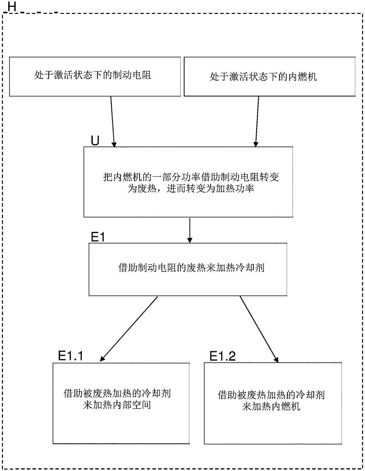
[0025] The dotted line very schematically represents an electric hybrid vehicle H, wherein the hybrid vehicle H has an internal combustion engine for burning fuel, an electric drive machine, and a coolant circuit which conducts coolant and surrounds the internal combustion engine. As usual, the internal combustion engine and the electric drive machine are used to drive the hybrid vehicle H, wherein the coolant circuit is firstly used as usual to cool the internal combustion engine. The internal combustion engine is preferably a diesel engine, whereby the fuel is preferably diesel.

[0026] A braking resistor is installed in the coolant circuit. The braking resistor generates waste heat in step E1 in order to heat the coolant.

[0027] The waste heat of the braking resistor is used in step E1.1 to heat the interior of the hybrid vehicle H via the coolant. In addition, the waste heat of the braking resistor can be used to heat the internal combustion engine via the coolant in ...


PUM


Abstract

The invention relates to an operating method, preferably control or regulation method, for a hybrid vehicle (H), with an internal combustion engine for burning fuel, an electric drive machine and a coolant-carrying, the internal combustion engine coolant circuit. The operating method is characterized in particular by the fact that in the coolant circuit, a braking resistor is installed and the braking resistor for heating the coolant generates waste heat (E1), wherein the waste heat of the braking resistor via the coolant for heating an interior of the hybrid vehicle (E1.1) and/or for heatingthe internal combustion engine (E1.2) is used and preferably the braking resistor thus acts as an auxiliary heater for the interior and/or the internal combustion engine.

Description

technical field [0001] The invention relates to an operating method, preferably a control or regulation method, in particular for an electric hybrid vehicle. The hybrid vehicle suitably includes: an internal combustion engine for driving the hybrid vehicle; an electric drive machine for driving the hybrid vehicle; and a coolant circuit which guides the coolant and surrounds the internal combustion engine. Background technique [0002] Hybrid vehicles achieve significant fuel savings compared to conventional, purely internal combustion engine driven vehicles. As a result of the fuel savings achieved, and in turn due to the improved efficiency, the internal combustion engine produces less waste heat, which is normally required to heat the vehicle interior. At low ambient temperatures (for example in winter), the reduced waste heat means that the internal combustion engine does not reach or only reaches its preferred operating temperature with a delay, so that, for example, th...

Claims


Application Information

Patent Timeline
Patent Type & Authority Applications(China)
IPC IPC(8): B60H1/03B60H1/04B60H1/00F01P7/14F01P3/20F02N19/10
CPCB60H1/004B60H1/03B60H1/04F01P3/20F01P7/14F02N19/10B60H1/00314B60H1/00371B60H1/034B60H1/2221B60H2001/2237F01P2037/02F01P2050/24F01P2060/06F01P2060/08
Inventor 马库斯·休伯特约翰内斯·皮特瑞德耶格·奥博迈耶安德鲁·布格
Owner MAN NUTZFAHRZEUGE AG
Why Eureka
Try Eureka