Sealed packing container

A technology for sealing packaging and containers, which is applied in the field of containers, can solve problems such as the instability of the anti-tripping structure and the decrease of sealing performance, and achieve the effects of stabilizing the anti-tripping structure, improving the sealing performance, and overcoming external extrusion or torsion

Inactive Publication Date: 2018-12-07
MEIYANG PLASTIC METALS PRODS QUANZHOU
View PDF12 Cites 1 Cited by
  • Summary
  • Abstract
  • Description
  • Claims
  • Application Information

AI Technical Summary

Problems solved by technology

Further, when the anti-tripping structure of this packaging container is unstable, its sealing performance will of course also decrease thereupon.

Method used


Image

  • Sealed packing container
  • Sealed packing container
  • Sealed packing container

Examples


Embodiment 1

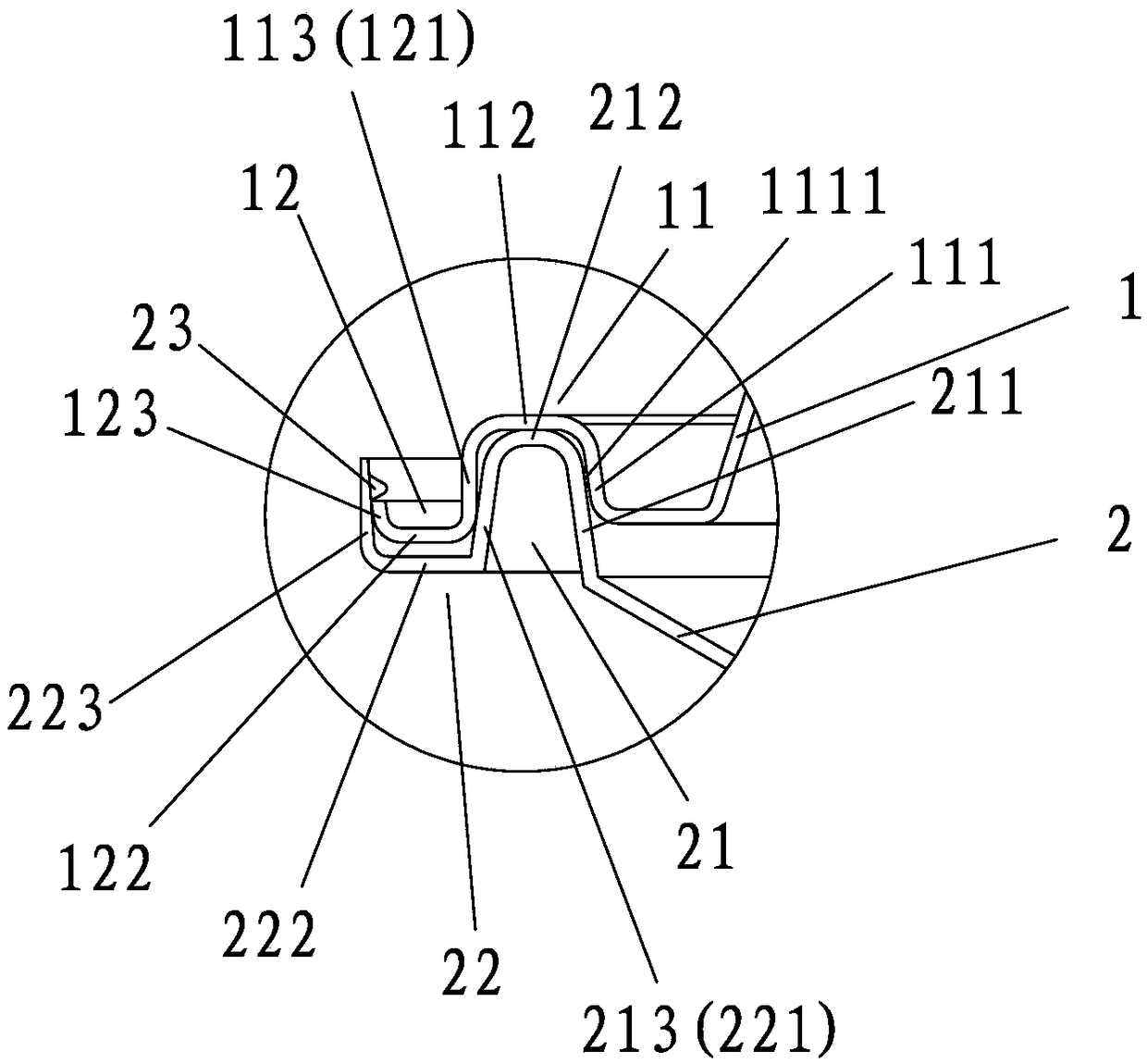
[0029] A kind of airtight packing container of the present invention, embodiment is as figure 1 As shown, it includes a box cover 1 and an open box body 2. The edge of the box cover 1 extends outwards and is provided with an annular first inner fitting groove 11 with a notch downward. The first inner fitting groove of the first inner fitting groove The lower end of the outer groove wall 113 is bent and extended outwards and upwards in turn to form an annular first outer fitting groove 12 with an upward notch; Shaped second inner fitting groove 21, the lower end of the outer groove wall 213 of the second inner fitting groove is bent and extended outwards and upwards in turn to form an annular second outer fitting groove 22 with the notch upward; The first inner fitting groove 11, the first outer fitting groove 12, the second inner fitting groove 21 and the second outer fitting groove 22 are elastic fitting grooves; the outer groove wall of the second outer fitting groove The i...

Embodiment 2

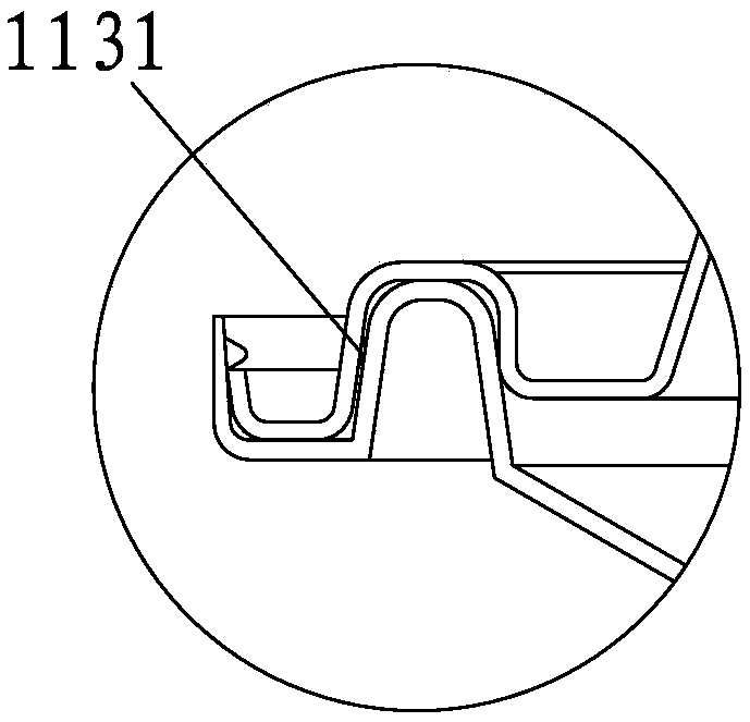
[0038] Such as figure 2 As shown, the difference between this embodiment and Embodiment 1 is that the inner groove wall of the first inner fitting groove 11 adopts a straight edge structure, the outer groove wall adopts a tapered surface structure, and the inner groove wall 111 of the first inner fitting groove 11 The first inner pressing part 1111 on the outer side of the first inner fitting groove 11 is replaced by the first outer pressing part 1131 on the inner side of the outer groove wall 113 of the first inner fitting groove 11, and the groove bottom 122 of the first outer fitting groove is aligned with the first outer fitting groove. The groove bottoms 222 of the second outer fitting grooves are in surface contact with each other and bonded together.

[0039] The first outer pressing member 1131 can adopt a closed-loop structure or an intermittent structure, and the intermittent structure can adopt a point shape or a zigzag shape.

[0040] When the first outer pressin...

Embodiment 3

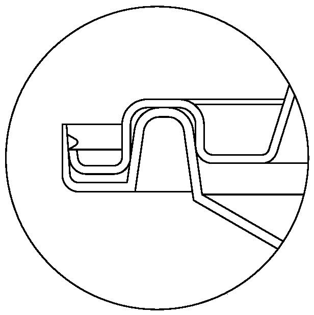
[0043] Such as image 3 As shown, the difference between this embodiment and the first embodiment is that the inner groove wall of the first inner fitting groove 11 adopts a straight edge structure, and the first inner pressing member 1111 is omitted. The arc transitions of the inner and outer groove walls of the first inner fitting groove 11 of the straight edge structure are respectively tangent to the inner and outer groove walls of the second inner fitting groove 21 to form an inner sealing structure and an outer sealing structure respectively. structure.


PUM


Abstract

The invention discloses a sealed packing container. The sealed packing container comprises a container cover and an opened container body; an annular first inner matching groove and an annular secondinner matching groove, with downward groove openings, are arranged on the edge of the container cover and the opening edge of the container body in an outward extending manner; the lower ends of outergroove walls of the first inner matching groove and the second inner matching groove are outwards and upwards bent to extend to form an annular first outer matching groove and an annular second outermatching groove with upward groove openings; the first inner matching groove, the first outer matching groove, the second inner matching groove and the second outer matching groove are all elastic matching grooves; the second inner matching groove is nested in the first inner matching groove; the first outer matching groove is nested in the second outer matching groove; and unfastening preventionstructures are provided. The inner groove wall of the first inner matching groove and the inner groove wall of the second inner matching groove, and/or the outer groove wall of the first inner matching groove and the outer groove wall of the second inner matching groove are in line contact in an elastic abutting mode. The packing container is higher in deformation resistance, more stable in unfastening prevention structure and better in sealing performance.

Description

technical field [0001] The invention relates to a container, in particular to a sealed packaging container. Background technique [0002] Traditional food containers or packaging containers, such as the sealed lunch boxes disclosed in patents such as Patent Nos. 86210848, 87216769, 89200752, and 94222756, have sealing devices composed of locking mechanisms such as buckles, buckles, and screws, and sealing elements. These designs are not only There are disadvantages such as complex structure and high cost, and it is not suitable for plastic and paper fast food boxes. Patent No. 89218416 discloses a plastic blister fast food box, which uses a self-locking structure of two concave-convex steps to replace the original product's planar fit, so that after the fast food box is closed, it is impossible to open without relying on the outside, and the sealing performance is improved . But when this fast food box is subjected to extrusion deformation, lid and box body fastening part ...

Claims


Application Information

Patent Timeline
Patent Type & Authority Applications(China)
IPC IPC(8): B65D43/06B65D43/08B65D53/00A45C11/20
CPCA45C11/20B65D43/065B65D43/08B65D53/00
Inventor 蔡啸杰蔡沧洋张冬阳庄跃新
Owner MEIYANG PLASTIC METALS PRODS QUANZHOU
Why Eureka
Try Eureka