Needle rod-pressure pin driving device applied to computer embroidering machine

A driving device and embroidery machine technology, which is applied in the field of embroidery machines, can solve problems affecting production efficiency, indentation of fabrics, and large impact force of fabrics, etc., and achieve the effects of simple and practical structure, reduced settings, and reduced movement space

Active Publication Date: 2018-12-07
陈启聪
View PDF7 Cites 3 Cited by
  • Summary
  • Abstract
  • Description
  • Claims
  • Application Information

AI Technical Summary

Problems solved by technology

In this way, the presser foot and the needle bar are driven by the main shaft at the same time, so when the presser foot is working, the presser foot presses the fabric at a high speed, which has a strong impact on the fabric, which can easily cause damage and tearing of the fabric. , It is also easy to produce indentations on the fabric. If these indentations are to be processed, the processing cost will be increased and the production efficiency will be affected at the same time

Method used


Image

  • Needle rod-pressure pin driving device applied to computer embroidering machine
  • Needle rod-pressure pin driving device applied to computer embroidering machine
  • Needle rod-pressure pin driving device applied to computer embroidering machine

Examples


Embodiment Construction

[0019] In order to make the purpose, technical solutions and advantages of the embodiments of the present invention more clear, the technical solutions in the embodiments of the present invention will be clearly and completely described below in conjunction with the drawings in the embodiments of the present invention.

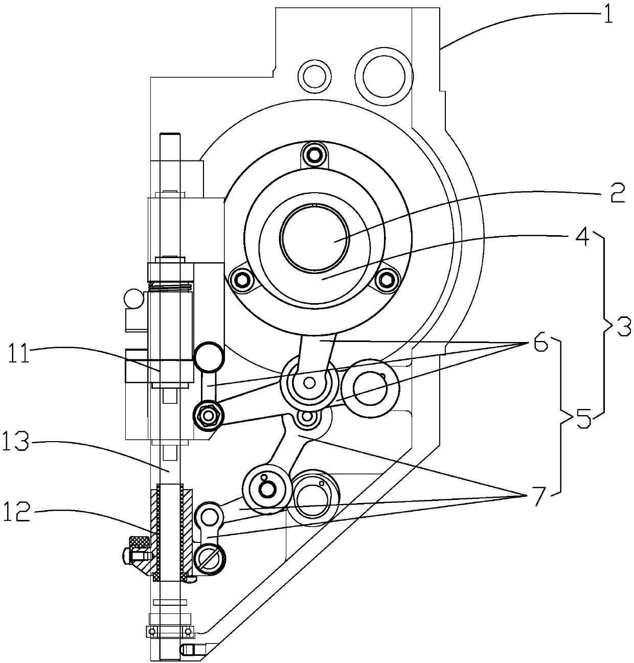
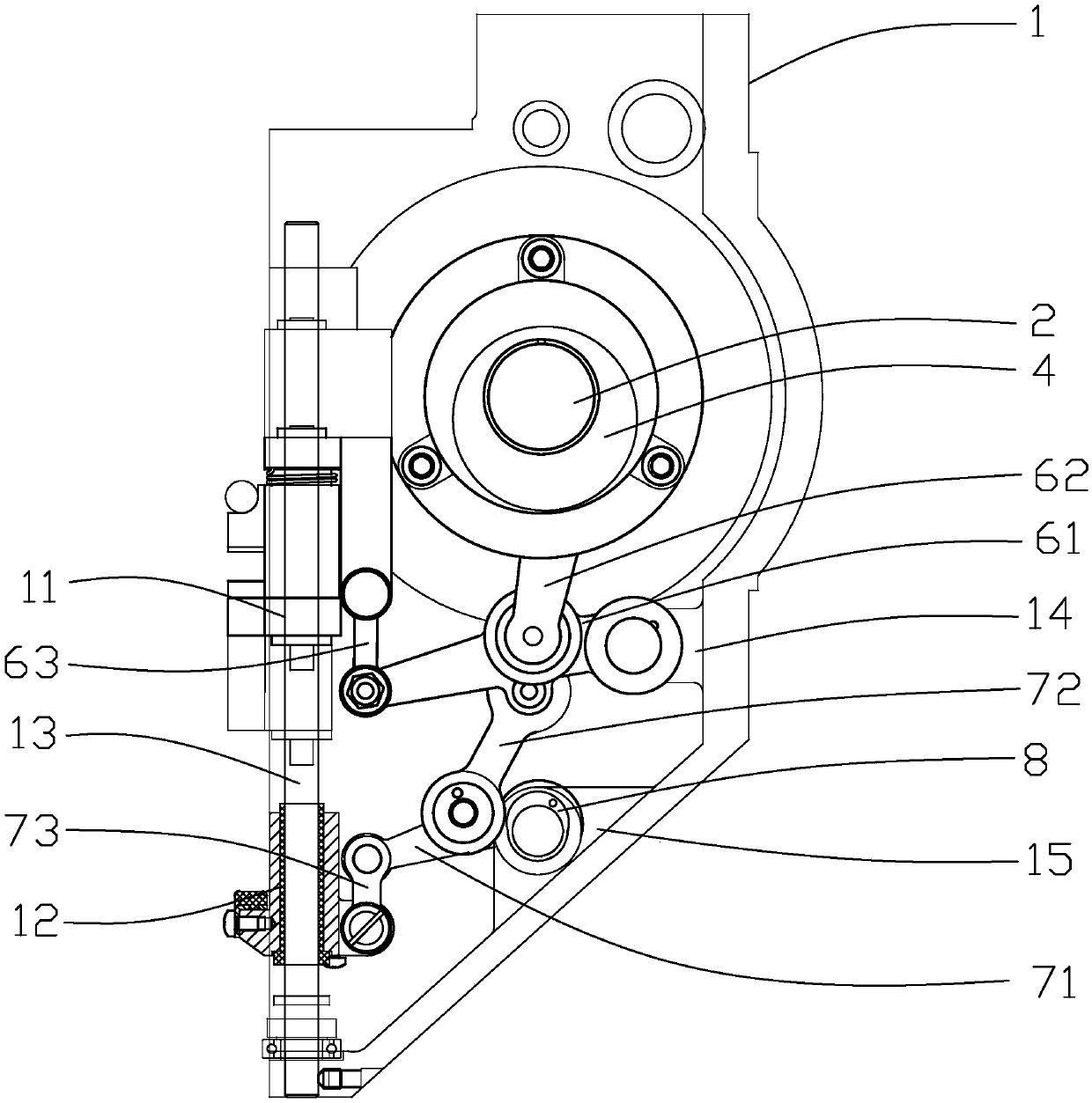
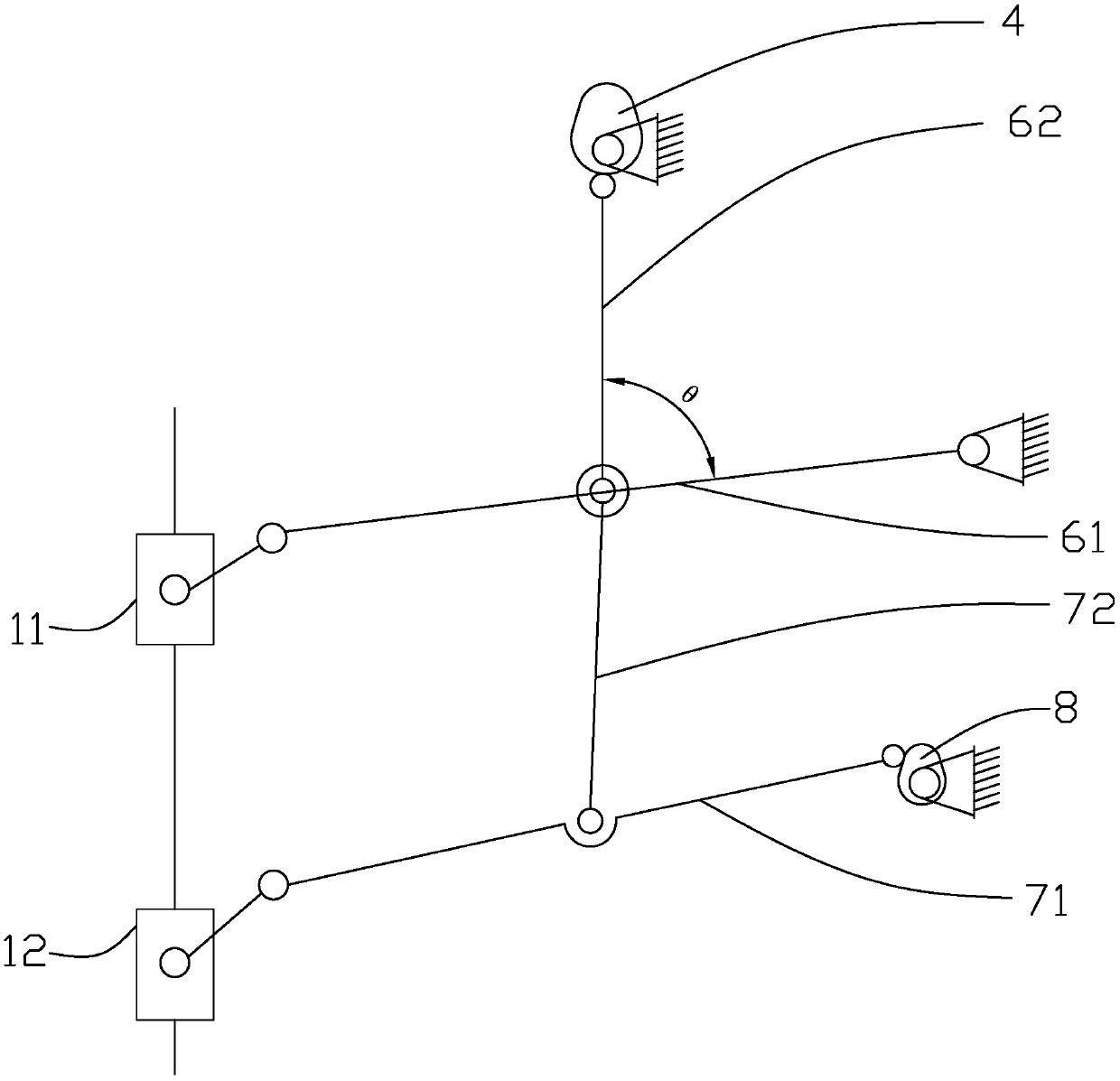
[0020] refer to figure 1 , a needle bar and presser foot driving device applied to a computerized embroidery machine, comprising a casing 1, a driving spindle 2 is arranged on the casing 1, and a driving mechanism 3 is arranged on the driving spindle 2. Further, the drive mechanism 3 includes a drive cam 4 mounted on the drive spindle 2 and a linkage mechanism 5 connected to the drive cam 4, and the linkage mechanism 5 includes a needle bar linkage mechanism 6 and a needle bar linkage mechanism for the movement of the needle bar 11. Presser foot linkage mechanism 7 for presser foot 12 movement. Still further, the driving cam 4 is connected with the needle bar...


PUM


Abstract

The invention relates to a needle rod-pressure pin driving device applied to a computer embroidering machine. The device comprises a shell and is characterized in that a driving mains shaft is arranged on the shell, wherein a driving mechanism is arranged on the driving main shaft and comprises a driving cam and a linkage mechanism, the driving cam is mounted on the driving main shaft, the linkagemechanism is connected with the driving cam and comprises a needle rod linkage mechanism and a pressure pin linkage mechanism, the needle rod linkage mechanism is used for driving a needle rod to move, and the pressure pin linkage mechanism is used for driving the pressure pin to move; the driving cam is connected with the needle rod linkage mechanism, and the pressure pin linkage mechanism is connected with the needle rod linkage mechanism; and a guide rail is further arranged on the shell, and the needle rod and the pressure pin are movably mounted on the guide rail through the driving mechanism. According to the needle rod-pressure pin driving device, the simultaneous movement of the needle rod and the pressure pin is realized; the driving mechanism is simple and practical, and drivingmechanisms required by the needle rod and the pressure pin are combined together, so that the arranged mechanical parts are reduced, meanwhile, the motion space required by the operation of the driving mechanism is reduced, and the production cost is effectively lowered.

Description

technical field [0001] The invention relates to the technical field of embroidery machines, in particular to a driving device for a needle bar and a presser foot applied to a computerized embroidery machine. Background technique [0002] The presser foot of the embroidery machine is driven by the needle bar through the presser foot spring to press the presser foot on the fabric, so that when the needle bar is retracted, the upper thread forms a thread loop at the nose of the needle, and the tip of the hook hooks the thread loop After one rotation, the bottom thread is caught, and then the upper thread is tightened, and the embroidery machine completes the most basic piercing action, producing a stitch on the cloth. Existing embroidery machines realize that the driving cams of the needle bar and the presser foot are all arranged on the same driving main shaft, and the driving main shaft drives the needle bar and the presser foot simultaneously. In this way, the presser foot ...

Claims


Application Information

Patent Timeline
Patent Type & Authority Applications(China)
IPC IPC(8): D05C11/06
CPCD05C11/06
Inventor 陈启聪
Owner 陈启聪
Why Eureka
Try Eureka