A recyclable steel cage

A technology of steel cages and main bars, applied in construction, connecting components, infrastructure engineering and other directions, can solve the problems of polluting the underground space environment, affecting underground construction, changing construction plans, etc., to reduce corrosion, save electricity, and simplify the production process. Effect

Active Publication Date: 2021-04-02
BEIJING JANDC GEOTECHNICAL CONSTR LTD
View PDF5 Cites 6 Cited by
  • Summary
  • Abstract
  • Description
  • Claims
  • Application Information

AI Technical Summary

Problems solved by technology

And now with the utilization and development of the underground space, the protection of the underground construction environment has attracted more and more attention. For example, in the shield construction of the subway, the support piles left in the previous foundation pit construction are often encountered, and the steel bars in them are The cage has brought a lot of inconvenience and difficulties to the shield construction of the subway, resulting in the change of the construction plan and the delay of the construction period.
Therefore, the retained steel cage is not only a waste of resources, but also affects the future underground construction and seriously pollutes the underground space environment

Method used


Image

  • A recyclable steel cage
  • A recyclable steel cage
  • A recyclable steel cage

Examples


Embodiment 1

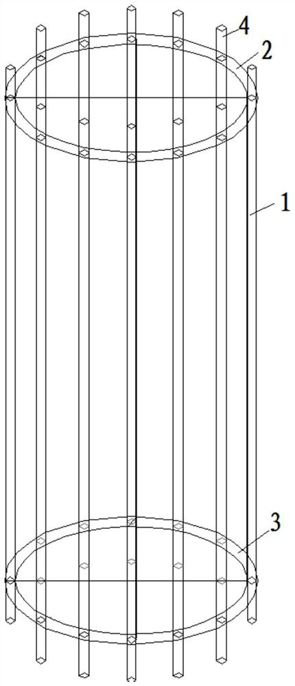
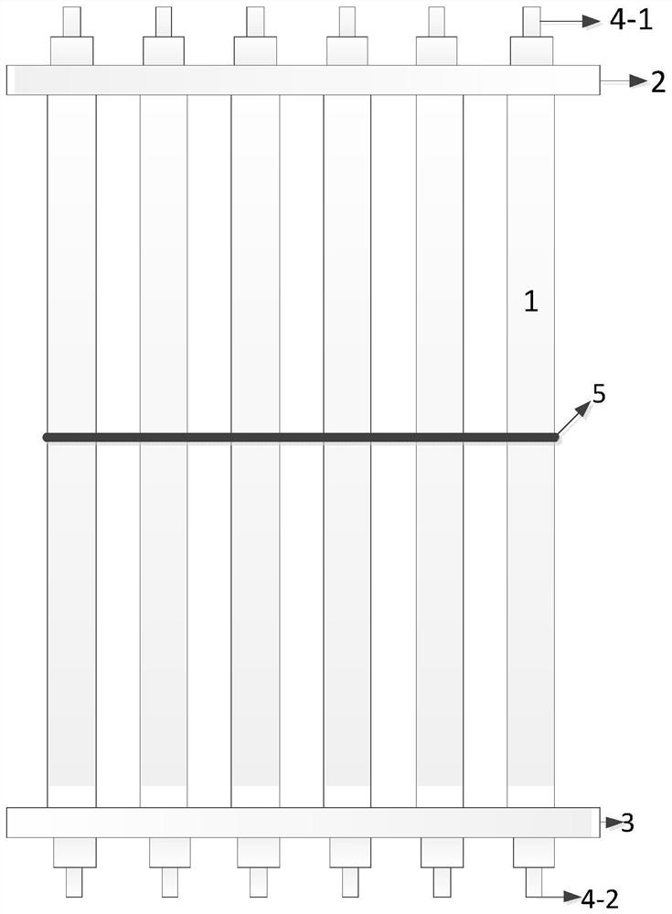
[0022] As shown in the figure, a recyclable reinforcement cage is characterized in that it includes a longitudinal main reinforcement (1), an upper flange (2), a lower flange (3) and a protective sleeve nut (4);

[0023] The upper flange (2) and the lower flange (3) are annular disks arranged in parallel, and holes are arranged on the annular disk, and the longitudinal main rib (1) can pass through the upper flange (2) and the lower flange plate (3), so that the longitudinal main ribs (1) are arranged in parallel;

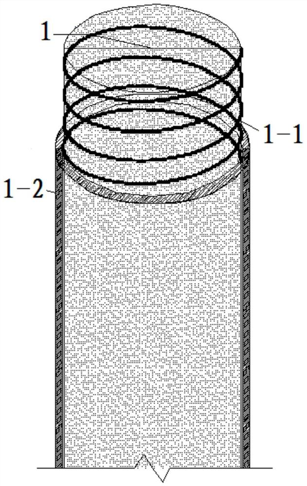
[0024] The parts of the upper and lower ends of the longitudinal main rib (1) protruding from the upper flange (2) and the lower flange (3) have thread (1-1), and the outside of the thread (1-1) has a nut protection sleeve ( 4).

[0025] The longitudinal main rib (1) is vertically arranged with the upper flange (2) and the lower flange (3).

[0026] The outer side of the longitudinal main rib (1) has a spacer sleeve (1-2).

[0027] The material of the isolation ...

Embodiment 2

[0034] As shown in the figure, a recyclable reinforcement cage is characterized in that it includes a longitudinal main reinforcement (1), an upper flange (2), a lower flange (3) and a protective sleeve nut (4);

[0035] The upper flange (2) and the lower flange (3) are annular disks arranged in parallel, and holes are arranged on the annular disk, and the longitudinal main rib (1) can pass through the upper flange (2) and the lower flange plate (3), so that the longitudinal main ribs (1) are arranged in parallel;

[0036] The parts of the upper and lower ends of the longitudinal main rib (1) protruding from the upper flange (2) and the lower flange (3) have thread (1-1), and the outside of the thread (1-1) has a nut protection sleeve ( 4).

[0037] The longitudinal main rib (1) is vertically arranged with the upper flange (2) and the lower flange (3).

[0038] The outer side of the longitudinal main rib (1) has a spacer sleeve (1-2).

[0039] The material of the isolation ...


PUM

PropertyMeasurementUnit
grafting efficiencyaaaaaaaaaa

Abstract

The invention discloses a recoverable reinforcement cage. The recoverable reinforcement cage is characterized by comprising longitudinal main ribs (1), an upper flange plate (2), a lower flange plate(3) and a protective cover nut (4); the upper flange plate (2) and the lower flange plate (3) are annular discs arranged in parallel; holes are formed in the annular discs; and the longitudinal main ribs (1) can penetrate through the upper flange plate (2) and the lower flange plate (3), so that the longitudinal main rib (1) are arranged in parallel. In the recoverable reinforcement cage, composite resin layers or PVC layers are wrapped on the longitudinal main ribs or rib bodies, so that the longitudinal main ribs can be pulled out after later casting is finished.

Description

technical field [0001] The invention relates to a recyclable reinforcement cage. Background technique [0002] In recent years, with the rapid development of cities, the construction of a large number of high-rise buildings and the development and utilization of urban underground spaces will inevitably bring about the excavation and support of large-scale foundation pit engineering. Due to the impact of the dense underground pipelines on the support construction and the limitation of the construction surface, and to protect its stability and the safety of the surrounding environment such as adjacent buildings and adjacent roads, pile-anchor support structure systems are often used in projects. And this kind of temporary support structure often adopts the form of concrete pouring pile, wherein the steel cage is an important part of the concrete pouring pile, which plays a very important role in the excavation process, but after the high-rise building foundation is completed a...

Claims


Application Information

Patent Timeline
Patent Type & Authority Patents(China)
IPC IPC(8): E02D5/34F16B37/00
CPCE02D5/34F16B37/00
Inventor 石健张钦喜李保坚李楷兵季东波张亚东云雷马利鑫马云龙石岩姚瀚康华兴张敏
Owner BEIJING JANDC GEOTECHNICAL CONSTR LTD
Why Eureka
Try Eureka