

Fan
A technology of fans and air ducts, applied in mechanical equipment, machines/engines, liquid fuel engines, etc., can solve the problems of single fan function and single ventilation function, and achieve the effect of avoiding deformation
- Summary
- Abstract
- Description
- Claims
- Application Information
AI Technical Summary
Problems solved by technology
Method used
Image

Examples
Embodiment 1
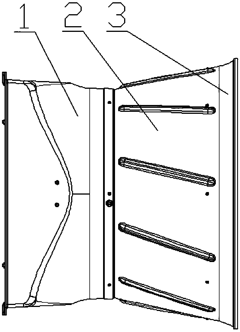
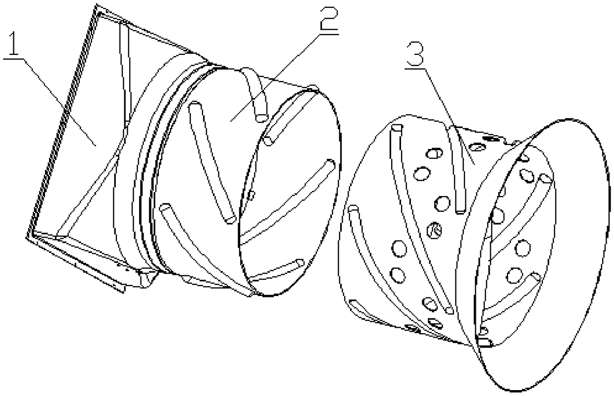
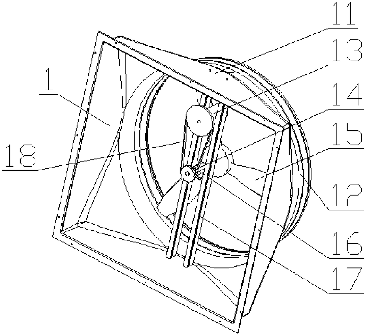
[0029] like Figure 1 to Figure 7 A fan, comprising a casing 1, an air collecting cylinder, a main fan blade 15 and a driving mechanism, the main fan blade 15 is located inside the air collecting cylinder, and is driven to work by the driving mechanism, and the driving mechanism is located inside the casing 1, and the wind collecting The cylinder includes a fixed cylinder 2 and an automatic rotating cylinder 3, the fixed cylinder 2 is fixed on one side of the casing 1, the automatic rotating cylinder 3 is slidably connected to the fixed cylinder 2 through several steel balls, and an auxiliary fan blade 36 is fixed on the inner wall of the automatic rotating cylinder 3; The driving mechanism includes a casing 1, a motor 13, a rotating shaft 14, a bearing 16, a bracket 17 and a belt 18. The motor 13 and the bearing 16 are fixed in the fan casing 11 through the bracket 17, and the bearing 16 is sleeved on the rotating shaft 14. One end of the rotating shaft 14 is fixed with a The...
Embodiment 2
[0032] On the basis of Example 1, as Figure 5-Figure 6 As shown, a number of air guide holes 32 are arranged between adjacent outer slideways 35. One side of the air guide holes 32 is welded with an air guide sheet 37. The air guide sheet 37 is arranged on the inner wall of the movable casing 31, and the air guide sheet 37 is open. It is arranged towards the fan blade 15; the air guide 37 is W-shaped; the sleeve connecting shell 12, the fixed shell 21 and the movable shell 31 are all cylindrical.
[0033] By arranging several air guide holes 32 between adjacent outer slideways 35, when the auxiliary fan blade 36 drives the moving casing 31 to partially move out of the fixed casing 21, the moving part of the moving casing 31 passes through the diameter of the moving casing 31 or the fixed casing 21. It is decided that the tilting phenomenon of the movable shell 31 will not occur after the movable shell 31 is moved out of the fixed shell 21, and it is best to set the air guide ...
Embodiment 3
[0035]On the basis of Embodiment 2, the end of the moving casing 31 away from the main fan blade 15 is provided with a horn diffuser 33; The distance between the outer rib 22, the inner slideway 24, the inner reinforcement rib 34 and the outer slideway 35 is spiral; the diameter of the air guide hole 32 is greater than 20mm; The distance is 1mm to 5mm.
[0036] By arranging the main fan blade 15 in the sleeve connecting shell 12, the distance between the edge of the main fan blade 15 and the inner wall of the sleeve connecting shell 12 during rotation can be reduced to increase the flow rate of the air flow. The distance between the sleeve connection shells 12 is controlled at 5mm to 10mm, so that the air flow rate generated by the rotation of the main fan blade 15 is in the best effect, and if the gap control is too large beyond 10mm, the air flow will decrease, which will lead to The negative pressure effect in the fixed casing 21 is reduced, and the reason for its occurren...
PUM
| Property | Measurement | Unit |
|---|---|---|
| diameter | aaaaa | aaaaa |
| diameter | aaaaa | aaaaa |
Abstract
Description
Claims
Application Information