Grate for high temperature gasification systems

a gasification system and high temperature technology, applied in the direction of combustible gas production, lighting and heating apparatus, combustion types, etc., can solve the problems of clogging the grate area, failing to effectively and efficiently process heterogeneous feed stocks, etc., to facilitate the regular and even flow of materials, promote understanding and appreciation, and reduce the size of any large pieces

Active Publication Date: 2013-06-13
INENTEC
View PDF9 Cites 13 Cited by
  • Summary
  • Abstract
  • Description
  • Claims
  • Application Information

AI Technical Summary

Benefits of technology

[0011]It is therefore an object of the present invention to provide an improved method and apparatus by which materials processed in one chamber of a high temperature system may be transferred to a second chamber of the high temperature system. It is a further object of the present invention to provide an improved method and apparatus by which materials processed in one chamber of a high temperature system may be crushed and reduced in size, thereby facilitating the transfer of those materials to a second chamber of the high temperature system. It is a further object of the present invention to provide an active grate wherein materials processed in one chamber of a high temperature system may agitated, thereby facilitating the flow of those materials to a second chamber of the high temperature system at a controlled rate. It is a further object of the present invention to provide an active grate in a waste treatment system interposed between a gasification unit capable of converting all or a portion of the organic components of a feed stream to a hydrogen rich gas and ash and a joule heated vitrification unit capable of converting inorganic materials and ash formed in the gasification unit into glass, and which, while not meant to be limiting, may further include a plasma capable of converting carbon and products of incomplete gasification formed in the gasification unit into a hydrogen rich gas.
[0015]The active grate of the present invention provides an advantage over prior art grates because as they are rotated, any pair of rockers alternately displaces material away from the active grate and then forms a void in the area between the rockers. In this manner, any material on top of the active grate is agitated up and allowed to fall down toward a void, thereby dispersing any large pieces across the upper surface of the active grate, and thus facilitating the regular and even flow of material through the active grate. Further, when the rockers are rotated from the first position to the second position, closing the void between them, any material in between these rockers is crushed between the adjacent edges of the rockers, thereby crushing and reducing the size of any large pieces, thus allowing their passage through the voids. This also facilitates the regular and even flow of material through the active grate.
[0016]Preferably, but not meant to be limiting, the active grate of the present invention is used in a combined gasification / vitrification waste treatment system. These systems consist of a gasification unit capable of converting all or a portion of the organic components of a feed stream to a hydrogen rich gas and ash and a joule heated vitrification unit capable of converting inorganic materials and ash formed in the gasification unit into glass. Preferably, but not meant to be limiting, the vitrification unit may further have a plasma capable of converting carbon and products of incomplete gasification formed in the gasification unit into a hydrogen rich gas. When used in a combined gasification / vitrification waste treatment system, the active grate of the present invention can effectively control and regulate an even rate of flow of materials from the gasification unit to the vitrification unit.
[0017]In these and other waste treatment systems wherein the active grate of the present invention can be advantageously deployed, the temperatures can be very high. These high temperatures can put a significant stain on the rockers of the active grate. Accordingly, it is preferred that the rockers include a coolant loop through the longitudinal axis of the rockers. By flowing a coolant through the coolant loop of the rockers, they can be maintained at a temperature that reduces the wear and tear on the rockers. Preferable coolants include, but are not limited to water, steam, ethylene glycol, paraffinic based heat transfer fluids, silicone based heat transfer fluids, and hydrocarbon heat transfer fluids. Water or other of these coolant fluids may be provided as a liquid, mist in a carrier gas, or steam. In this manner, the cooling effects of the water can be realized without generating excessive pressure changes in the rockers.

Problems solved by technology

One difficulty that the combined system was designed to overcome was the failure of prior art systems to effectively and efficiently process heterogeneous feed stocks.
This, in turn, causes more rapid oxidation of the materials in the unplugged sections, and slower oxidation of the plugged sections, further exacerbating the problem as the more oxidized portions are reduced in size and thus generally flow through the grate while the less oxidized portions are not reduced, and tend to add to the clogged area of the grate.

Method used


Image

  • Grate for high temperature gasification systems
  • Grate for high temperature gasification systems
  • Grate for high temperature gasification systems

Examples


Embodiment Construction

[0023]For the purposes of promoting an understanding of the principles of the invention, reference will now be made to the embodiments illustrated in the drawings. Specific language will be used to describe the same, and like reference numbers will refer to like components of the invention. It will nevertheless be understood that no limitations of the inventive scope is thereby intended, as the scope of this invention should be evaluated with reference to the claims appended hereto. Alterations and further modifications in the illustrated devices, and such further applications of the principles of the invention as illustrated herein are contemplated as would normally occur to one skilled in the art to which the invention relates.

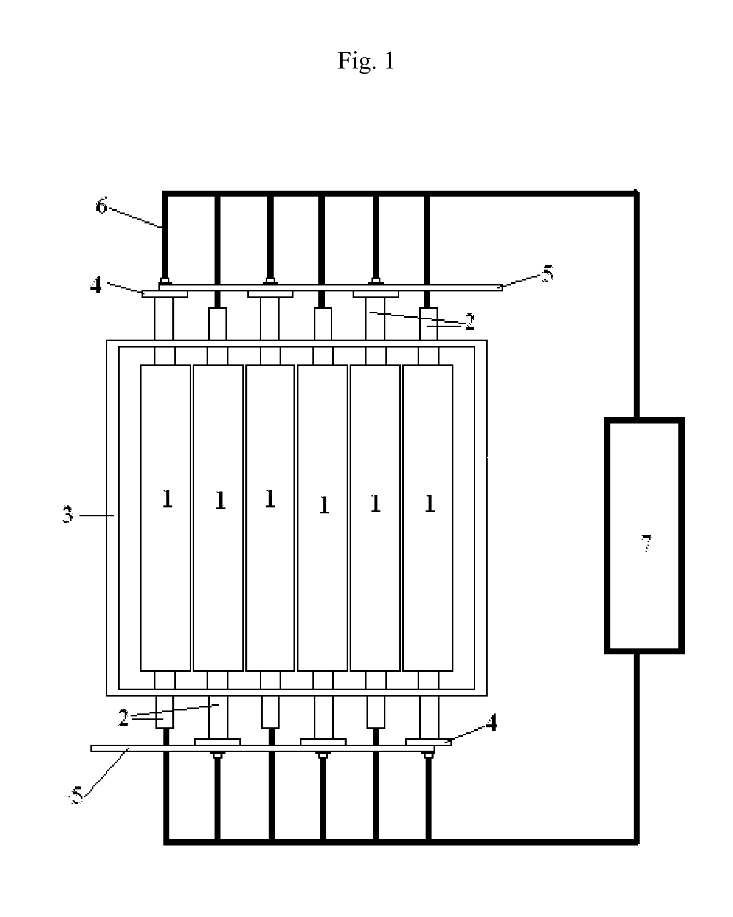
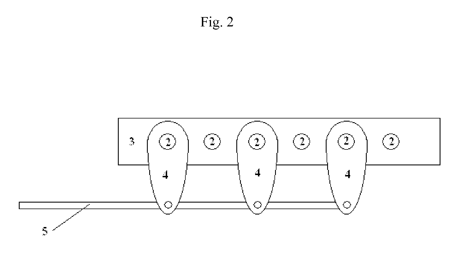
[0024]For the purposes of promoting an understanding of the principles of the invention, FIG. 1 is an overhead view of a preferred embodiment of the active grate of the present invention and FIG. 2 is a side view of the same preferred embodiment of the activ...


PUM

PropertyMeasurementUnit
crushing forceaaaaaaaaaa
temperatureaaaaaaaaaa
energyaaaaaaaaaa

Abstract

An improved active grate consisting of at least two elongated rockers positioned parallel to one and another, each rocker having a lower surface and an upper surface and configured to rotate back and forth about their longitudinal axis. Each individual rocker is further configured to rotate in the opposite direction of the adjacent rockers such that any pair of adjacent rockers alternately forms a void allowing material to pass through active grate when rotating in one direction into a first position, and closes the void when rotated in the opposite direction in a second position. The active grate finds particular utility in a combined gasification / vitrification waste treatment system, where it is used to pass partially oxidized materials from a gasification chamber to a vitrification chamber. The rockers include a coolant loop through the longitudinal axis of the rockers.

Description

TECHNICAL FIELD[0001]The present invention relates generally to a methods and apparatus for processing feedstocks containing organic materials. More specifically, the present invention relates to a grate particularly suited to use in partial oxidation gasification systems. The present invention finds particularly utility when used in an integrated partial oxidation gasification and vitrification system used for recovering the energy value from the organic portions of heterogeneous feedstocks while converting the inorganic portions to a safe and useable form.BACKGROUND OF THE INVENTION[0002]U.S. patent application Ser. No: 11 / 432,826, filed May 12, 2006 and entitled “COMBINED GASIFICATION AND VITRIFICATION SYSTEM” (hereafter the “combined system” and incorporated in its entirety herein by this reference) disclosed an improved method for processing organic and heterogeneous feedstocks. The description of the combined system describes a system that is capable of treating mixtures of in...

Claims


Application Information

Patent Timeline
Patent Type & Authority Applications(United States)
IPC IPC(8): C10J3/72B01J19/00C10J3/46
CPCC10J3/40C10J2300/0946C10J2300/1634F23H13/08F23G5/0276F23H9/08F23G5/002
Inventor SURMA, JEFFREY E.BATDORF, JAMES A.
Owner INENTEC
Why Eureka
Try Eureka