
Wind driven generator bearing automatic lubricating device and automatic lubricating control method

A wind turbine, automatic lubrication technology, applied in the direction of engine lubrication, safety devices, engine components, etc., can solve the problems of uneven grease injection, difficult discharge of waste grease, saponification of waste grease, etc., and achieve the effect of accurate lubrication.

Active Publication Date: 2018-12-07
CSIC CHONGQING HAIZHUANG WINDPOWER EQUIP
View PDF16 Cites 7 Cited by
  • Summary
  • Abstract
  • Description
  • Claims
  • Application Information

AI Technical Summary

Problems solved by technology

[0003] In view of this, the problem to be solved by the present invention is to provide an automatic lubricating device and an automatic lubrication control method for wind-driven generator bearings, so as to solve the problem of using the existing grease injection equipment and method to inject less grease each time, waste grease is not easily discharged, It is easy to cause saponification of waste oil and block the oil circuit. When the unit is shut down and the power is not turned off, timing will also cause problems such as uneven grease injection and inaccurate grease injection.

Method used


Image

  • Wind driven generator bearing automatic lubricating device and automatic lubricating control method
  • Wind driven generator bearing automatic lubricating device and automatic lubricating control method
  • Wind driven generator bearing automatic lubricating device and automatic lubricating control method

Examples


Embodiment Construction

[0024] Embodiments of the technical solutions of the present invention will be described in detail below in conjunction with the accompanying drawings. The following examples are only used to illustrate the technical solutions of the present invention more clearly, and therefore are only examples, rather than limiting the protection scope of the present invention.

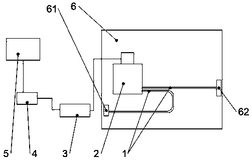
[0025] see figure 1 , the present embodiment provides an automatic lubricating device for wind turbine bearings, including a lubricating pump 2 installed on the generator 6, a lubricating oil pipe 1, an auxiliary junction box 3, a contactor 4, and a controller 5. The lubricating pump 2 is A power signal line and a fault alarm signal line are provided, and the power signal line and the fault alarm signal line are electrically connected to the auxiliary junction box 3, the auxiliary junction box 3 is electrically connected to the contactor 4, and the switch joint of the contactor 4 is connected to the controller 5 e...


PUM


Abstract

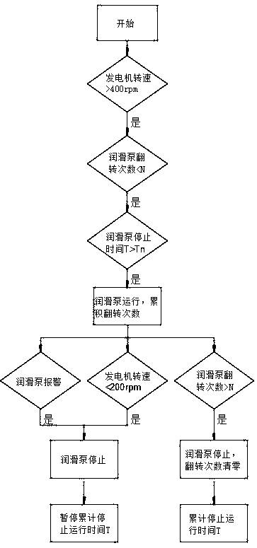
The invention discloses a wind driven generator bearing automatic lubricating device and an automatic lubricating control method. The wind driven generator bearing automatic lubricating device comprises a lubricating pump installed on a generator, a lubricating oil pipe, an auxiliary junction box, a contactor and a controller. The lubricating pump is provided with a power signal line and a fault warning signal line. The power signal line and the fault warning signal line are in electric connection with the auxiliary junction box. The auxiliary junction box is in electric connection with the contactor. A contactor switch connector is in electric connection with the controller. According to the lubricating method of the wind driven generator bearing automatic lubricating device, the controller is used for obtaining the rotation speed of the generator, for recording the number of times of overturning of the lubricating pump, for recording stop time T of the lubricating pump, and for recording temperature data of a bearing. The lubricating pump is started and stopped according to setting, and the problems that a current automatic lubricating system is liable to cause oil separation andsaponification, consequently a lubricating oil way is blocked or the grease outlet amount is not enough are solved, and meanwhile the problems that when the generator does not rotate, grease is alsoconveyed in, timing is also conducted under the circumstance that a unit is stopped without power failure, grease is conveyed in unevenly, and the grease filling amount is inaccurate are avoided.

Description

technical field [0001] The invention relates to the technical field of wind power generation, in particular to an automatic lubricating device and an automatic lubricating control method for wind power generator bearings. Background technique [0002] At present, there are two modes of injecting grease into the bearings of large wind turbines: (1) Manual grease gun is used to regularly inject grease into the bearing chamber of the generator through the grease nozzle and oil delivery pipe manually, and the amount of grease injection and the injection time interval are controlled manually. Its advantage is that the amount of single grease injection is large, and the waste grease is fully discharged. The disadvantage is that the injection time interval and injection volume are not easy to control, and it is easy to cause the bearing to run under the condition of excess grease or lack of oil, resulting in bearing failure; in addition, the generator is generally in a static state...

Claims


Application Information

Patent Timeline
IPC IPC(8): F16N7/38F16N29/04F16N29/02
CPCF16N7/38F16N29/02F16N29/04F16N2260/02Y02E10/72
Inventor 蔡梅园聂思宇陈薛梅雷春宇刘淑芳邓川林杜炜罗元宏张迁秦鑫杨静
Owner CSIC CHONGQING HAIZHUANG WINDPOWER EQUIP
Learn More