
Traveling wave antenna synthetic aperture radar imaging method

A technology of synthetic aperture radar and imaging method, applied in radio wave measurement systems, radio wave reflection/re-radiation, utilization of re-radiation, etc., can solve the radar imaging Doppler blur, radar echo Doppler spectrum broadening, limitation Traveling wave antenna application and other issues to achieve the effect of avoiding timing

Active Publication Date: 2020-11-20
NAT SPACE SCI CENT CAS
View PDF5 Cites 0 Cited by
  • Summary
  • Abstract
  • Description
  • Claims
  • Application Information

AI Technical Summary

Problems solved by technology

When beam dispersion occurs in the azimuth direction, it will cause the Doppler spectrum of the radar echo to broaden, resulting in Doppler ambiguity in radar imaging, which limits the application of traveling wave antennas in synthetic aperture radars

Method used


Image

  • Traveling wave antenna synthetic aperture radar imaging method
  • Traveling wave antenna synthetic aperture radar imaging method
  • Traveling wave antenna synthetic aperture radar imaging method

Examples


Embodiment Construction

[0053] The technical solution of the present invention will be described in detail below in conjunction with the accompanying drawings.

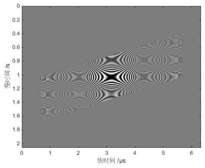
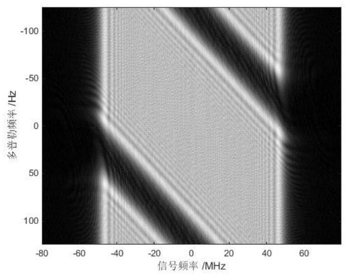
[0054] The most common form of transmitted signal for SAR is the chirp. The beam dispersion phenomenon of traveling-wave antennas means that within each chirp, the beam pointing changes regularly over time. Taking front-looking and side-looking synthetic aperture radar as an example, when there is beam dispersion in the azimuth direction, in addition to the way that the center frequency of the signal can maintain the side-looking, different squints will appear at other frequencies. Taking positive oblique angles at high frequencies and negative oblique angles at low frequencies as an example, figure 1 The time-domain signal diagram of the echo of a point target is shown. It can be seen that the "shape" of the radar echo matrix first changes, and its outline is no longer a rectangle but similar to a parallelogram. figure 2 The two-dimensio...


PUM


Abstract

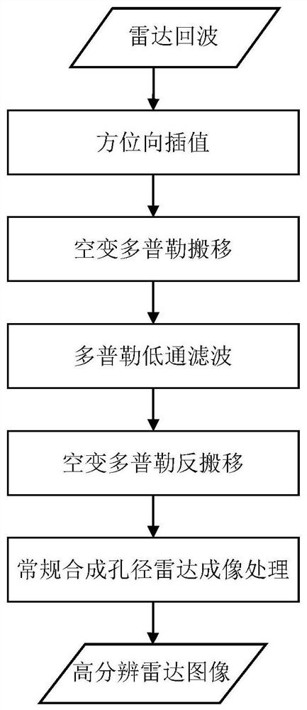
The invention discloses a traveling wave antenna synthetic aperture radar imaging method. The method comprises the steps that azimuth interpolation is performed on radar echoes; space-variant Dopplershift is conducted on the interpolated radar echo, and different Doppler spectrums of each frequency in a signal frequency band are shifted to a baseband; low-pass filtering is carried out on the shifted Doppler spectrum to obtain an unambiguous baseband Doppler spectrum; space-variant Doppler inverse migration is carried out on the unambiguous baseband Doppler spectrum to obtain a signal with anunambiguous original Doppler spectrum; and synthetic aperture radar imaging processing is carried out on the signal with the unambiguous original Doppler spectrum to obtain a high-resolution radar image. According to the method, the Doppler ambiguity problem of the synthetic aperture radar caused by beam dispersion of the traveling wave antenna can be solved without increasing the pulse repetitionfrequency (PRF) of a radar system, so that the time sequence, power consumption and data rate pressure brought to the radar system by increasing the PRF are avoided.

Description

technical field [0001] The invention relates to the field of synthetic aperture radar signal processing, in particular to a traveling wave antenna synthetic aperture radar imaging method. Background technique [0002] Traveling wave antenna is a simple and common antenna form, which belongs to frequency scanning antenna, and its main beam direction changes with the change of antenna operating frequency, that is, the beam has dispersion characteristics. Compared with the standing wave antenna, the traveling wave antenna has a wider impedance bandwidth and better directional radiation characteristics, and at the same time has a lower cost, and its application field is very wide. When the traveling wave antenna is applied to the synthetic aperture radar, especially the high-resolution broadband synthetic aperture radar, the influence of beam dispersion needs to be considered. High-resolution synthetic aperture radar usually uses broadband signals to obtain high resolution in t...

Claims


Application Information

Patent Timeline
IPC IPC(8): G01S13/90
CPCG01S13/9011G01S13/90
Inventor 翟文帅张云华
Owner NAT SPACE SCI CENT CAS
Learn More