Battery sampling system

A battery sampling and battery technology, which is applied in the direction of measuring electricity, measuring electrical variables, measuring devices, etc., can solve the problems of poor conversion accuracy, incompetence for low-power applications, unbalanced battery cells, etc., and achieves high reliability. Effect

Pending Publication Date: 2018-12-07
CRM ICBG (WUXI) CO LTD
View PDF9 Cites 5 Cited by
  • Summary
  • Abstract
  • Description
  • Claims
  • Application Information

AI Technical Summary

Problems solved by technology

[0012] In view of the above-mentioned shortcomings of the prior art, the purpose of the present invention is to provide a battery sampling system, which is used to solve the large power consumption in the battery pack voltage detection circuit in the prior art, which is not suitable for low-power applications, and the conversion The problem of poor accuracy and the problem of unbalanced cells in the battery pack

Method used


Image

  • Battery sampling system
  • Battery sampling system
  • Battery sampling system

Examples


Embodiment 1

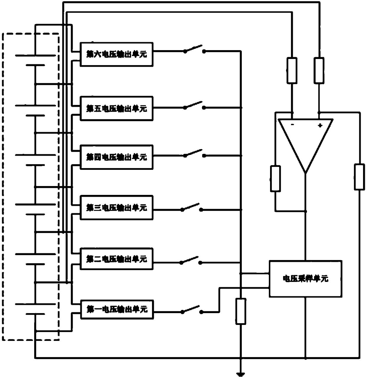
[0068] Such as Figure 4 As shown, the present embodiment provides a battery sampling system, and the sampling system 20 includes:

[0069] A battery pack 21, comprising the lowest battery, the second battery and the highest battery connected in series in sequence;

[0070] The lowest battery sampling circuit 22 is connected to the positive terminal, the negative terminal of the lowest battery and the positive terminal of the highest battery, and is used to draw a sampling current from the positive terminal of the highest battery, and transfer the lowest battery The battery voltage VB1 is converted to ground voltage for output;

[0071] The highest battery sampling circuit 23 is connected with the negative terminal of the lowest battery, the positive terminal of the second battery and the positive terminal of the highest battery, for sampling from the positive terminal of the highest battery current, and convert the voltage VB3 of the highest cell into a ground voltage for o...

Embodiment 2

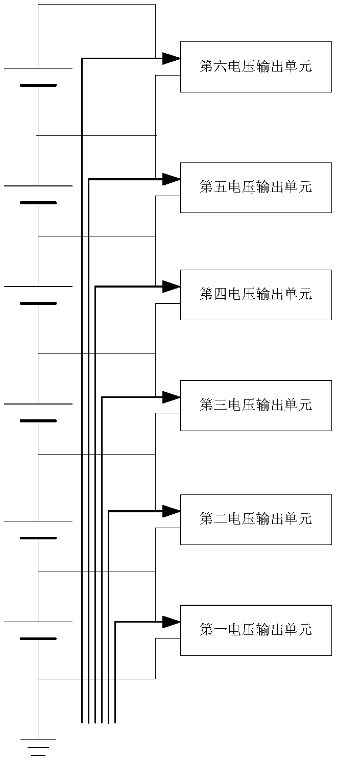
[0092] Such as Figure 5 As shown, the present embodiment provides a battery sampling system, and the sampling system 20 includes:

[0093] A battery pack 21, comprising the lowest battery, the second battery and the highest battery connected in series in sequence;

[0094] The lowest battery sampling circuit 22 is connected to the positive terminal, the negative terminal of the lowest battery and the positive terminal of the highest battery, and is used to draw a sampling current from the positive terminal of the highest battery, and transfer the lowest battery The battery voltage VB1 is converted to ground voltage for output;

[0095] The highest battery sampling circuit 23 is connected with the negative terminal of the lowest battery, the positive terminal of the second battery and the positive terminal of the highest battery, for sampling from the positive terminal of the highest battery current, and convert the voltage VB3 of the highest cell into a ground voltage for o...


PUM


Abstract

The invention provides a battery sampling system which comprises a battery pack with the series connection of a lowest battery, a second battery and a highest battery, a lowest battery sampling circuit corresponding to the lowest battery, a highest battery sampling circuit corresponding to the highest battery, a second battery sampling circuit corresponding to the second battery, and a current dynamic automatic-compensation circuit for dynamically and automatically compensating the sampling current input into the second battery sampling circuit. According to the battery sampling system provided by the invention, the problems of high power consumption, incapability of running low-power-consumption application, poor conversion precision and unbalanced cells in the battery pack in a battery pack voltage detecting circuit in the prior art are overcome.

Description

technical field [0001] The invention belongs to the technical field of circuit design, in particular to a battery sampling system. Background technique [0002] At present, there are mainly two methods for battery pack voltage detection: lithium battery pack voltage detection system based on battery sampling circuit and battery pack voltage detection system based on switch network: battery pack voltage detection system based on battery sampling circuit such as figure 1 As shown, the system converts the voltage of each battery in the battery pack to the ground voltage through the battery sampling circuit, and then outputs the required battery cell voltage through the operational amplifier after passing through the data selector; among them, each battery sampling circuit also needs The sampling current is consumed from the respective positive terminals of the corresponding batteries, as Figure 2a shown; and the specific circuit of the battery sampling circuit is generally as...

Claims


Application Information

Patent Timeline
Patent Type & Authority Applications(China)
IPC IPC(8): G01R31/36
CPCG01R31/36
Inventor 尤勇罗丙寅刘亚彬李建民
Owner CRM ICBG (WUXI) CO LTD
Why Eureka
Try Eureka