
Planar circularly polarized electronic tag

An electronic label, circular polarization technology, applied in the field of radio frequency identification, can solve the problems of low correlation, limit application scenarios, reduce user experience, etc., achieve high bandwidth, reduce impact, and improve data communication.

Inactive Publication Date: 2018-12-07
华大恒芯科技有限公司
View PDF7 Cites 0 Cited by
  • Summary
  • Abstract
  • Description
  • Claims
  • Application Information

AI Technical Summary

Problems solved by technology

In practical applications, this type of electronic tag has a large polarization loss of about 3dBi, which limits its application scenarios and reduces user experience
[0004] On the contrary, the sensitivity of circularly polarized antennas has a lower correlation with the direction of signal reception, but circularly polarized antennas are rarely used in RFID tags in practical applications.
Furthermore, in limited circularly polarized transponder applications, the correlation between the sensitivity and the direction of application and / or placement is still not low enough to be satisfactory

Method used


Image

  • Planar circularly polarized electronic tag
  • Planar circularly polarized electronic tag
  • Planar circularly polarized electronic tag

Examples


Embodiment Construction

[0026] It should be noted that components in the various figures may be shown exaggerated for the purpose of illustration and are not necessarily true to scale. In the various figures, identical or functionally identical components are assigned the same reference symbols.

[0027] In the present invention, unless otherwise specified, "arranged on", "arranged on" and "arranged on" do not exclude the presence of intermediates between the two.

[0028] In the present invention, each embodiment is only intended to illustrate the solutions of the present invention, and should not be construed as limiting.

[0029] In the present invention, unless otherwise specified, the quantifiers "a" and "an" do not exclude the scene of multiple elements.

[0030] It should also be pointed out that in the embodiments of the present invention, for the sake of clarity and simplicity, only a part of components or components may be shown, but those skilled in the art can understand that under the t...


PUM


Abstract

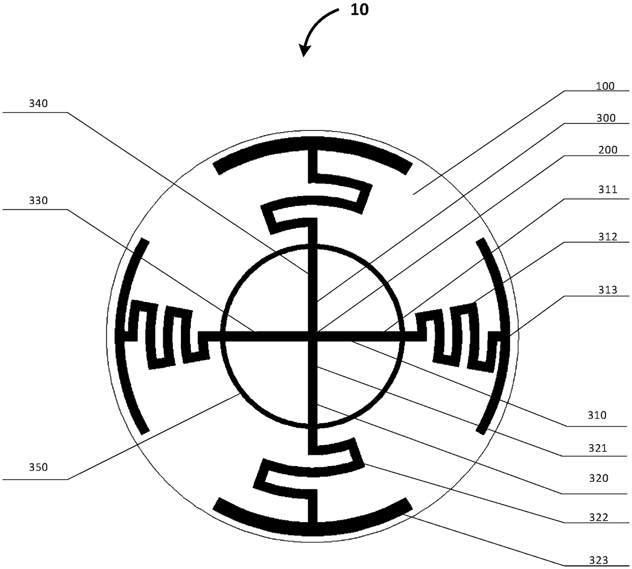
The invention relates to a planar circularly polarized electronic tag, which comprises a substrate, an antenna and a chip, wherein the substrate is used for accommodating the chip and the antenna; theantenna has a short circuit ring, a first antenna oscillator and a second antenna oscillator, each of the first antenna oscillator and the second antenna oscillators has two dipole arms that are conductively connected with each other, the first antenna oscillator and the second antenna oscillator are connected with each other and arranged in a crossing manner, so that the dipole arms are arrangedat an interval of 90 degrees, and the size of the dipole arms is set such that a phase difference between the adjacent dipole arms is 90 degrees; and the chip is matched with the antenna, and is arranged at a connecting point of the first antenna oscillator and the second antenna oscillator. By adopting the electronic tag, the polarization loss can be greatly reduced. In addition, the planar circularly polarized electronic tag further has high bandwidth and is capable of flexibly setting parameters such as impedance, geometrical shape, operating frequency and the like.

Description

technical field [0001] The present invention generally relates to the field of radio frequency identification (RFID), in particular to a planar circularly polarized electronic tag. Background technique [0002] With the rise of the Internet of Things, as one of the key technologies, RFID (Radio Frequency Identification) technology has been widely used in daily life, such as in logistics, anti-counterfeiting, transportation, warehousing and other fields. One of the key parameters of RFID technology is the sensitivity of RFID electronic tags, which directly determines the application occasions and application prospects of RFID technology in Internet of Things technology. [0003] At present, RFID electronic tags mainly use linearly polarized antennas. Since the sensitivity of the linearly polarized antenna is highly correlated with the signal receiving direction, the sticking direction of the RFID electronic tag using the linearly polarized antenna must match the signal recei...

Claims


Application Information

Patent Timeline
Patent Type & Authority Applications(China)
IPC IPC(8): G06K19/077
CPCG06K19/07773
Inventor 马纪丰
Owner 华大恒芯科技有限公司
Learn More