
Directional diagram and polarization reconstructable antenna

A technology for reconstructing antenna and pattern, which is applied to antenna unit combinations, antennas, antenna arrays and other directions with different polarization directions, to achieve the effect of low profile, small gain fluctuation, and easy integration

Inactive Publication Date: 2018-12-07
SOUTHEAST UNIV
View PDF2 Cites 1 Cited by
  • Summary
  • Abstract
  • Description
  • Claims
  • Application Information

AI Technical Summary

Problems solved by technology

[0002] The rapid development of wireless communication technology puts forward higher requirements for system requirements. Traditional single-function antennas cannot meet the current needs very well and become a bottleneck restricting the development of system performance.

Method used


Image

  • Directional diagram and polarization reconstructable antenna
  • Directional diagram and polarization reconstructable antenna
  • Directional diagram and polarization reconstructable antenna

Examples


Embodiment Construction

[0023] The technical solution of the present invention will be further introduced below in combination with specific embodiments.

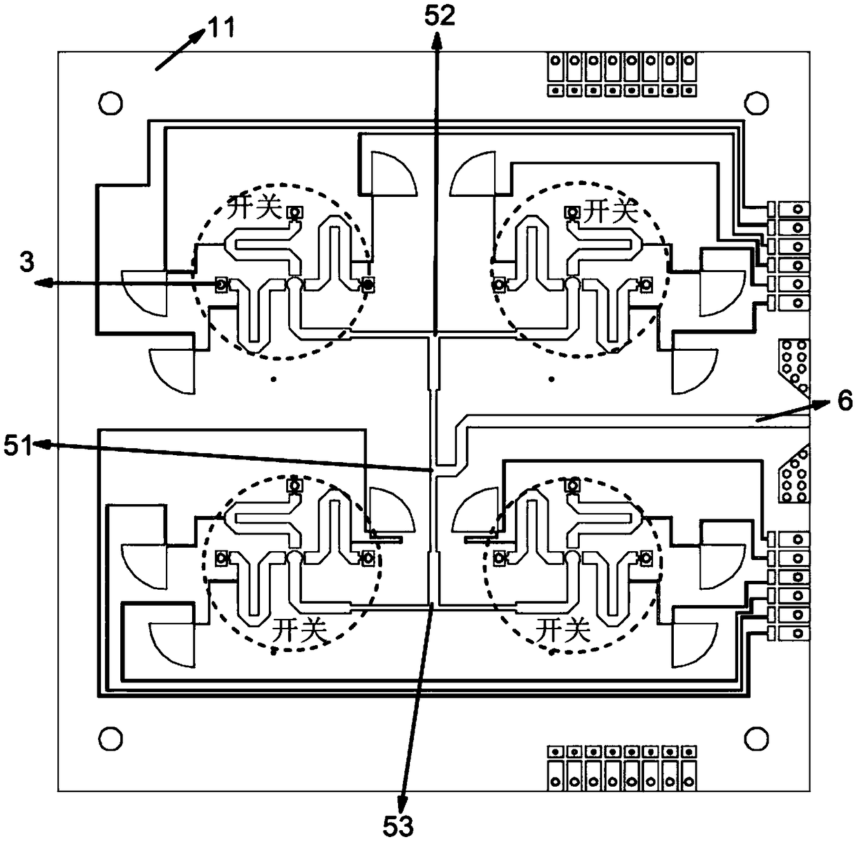
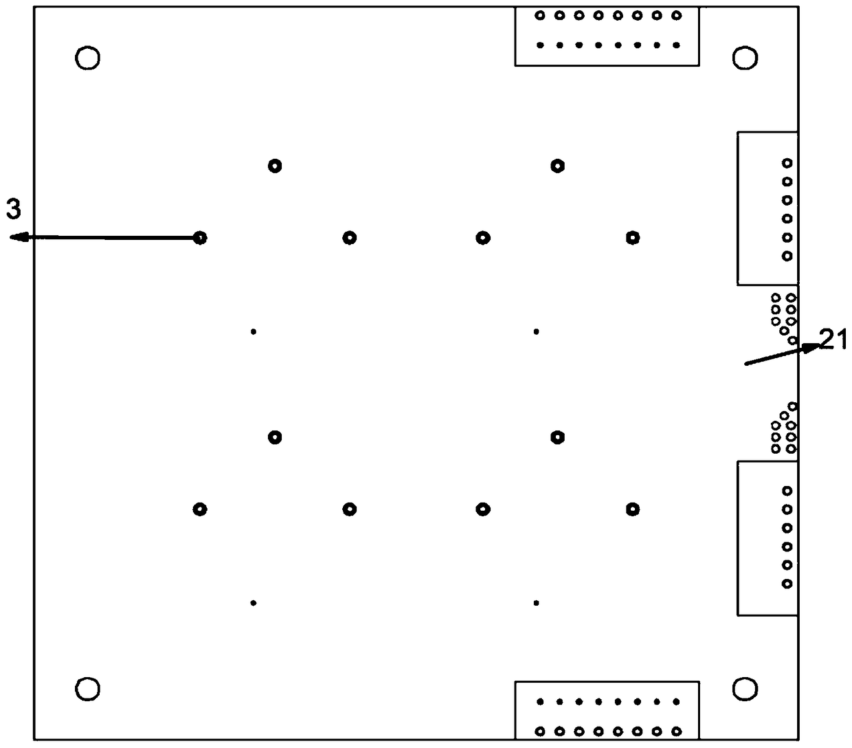
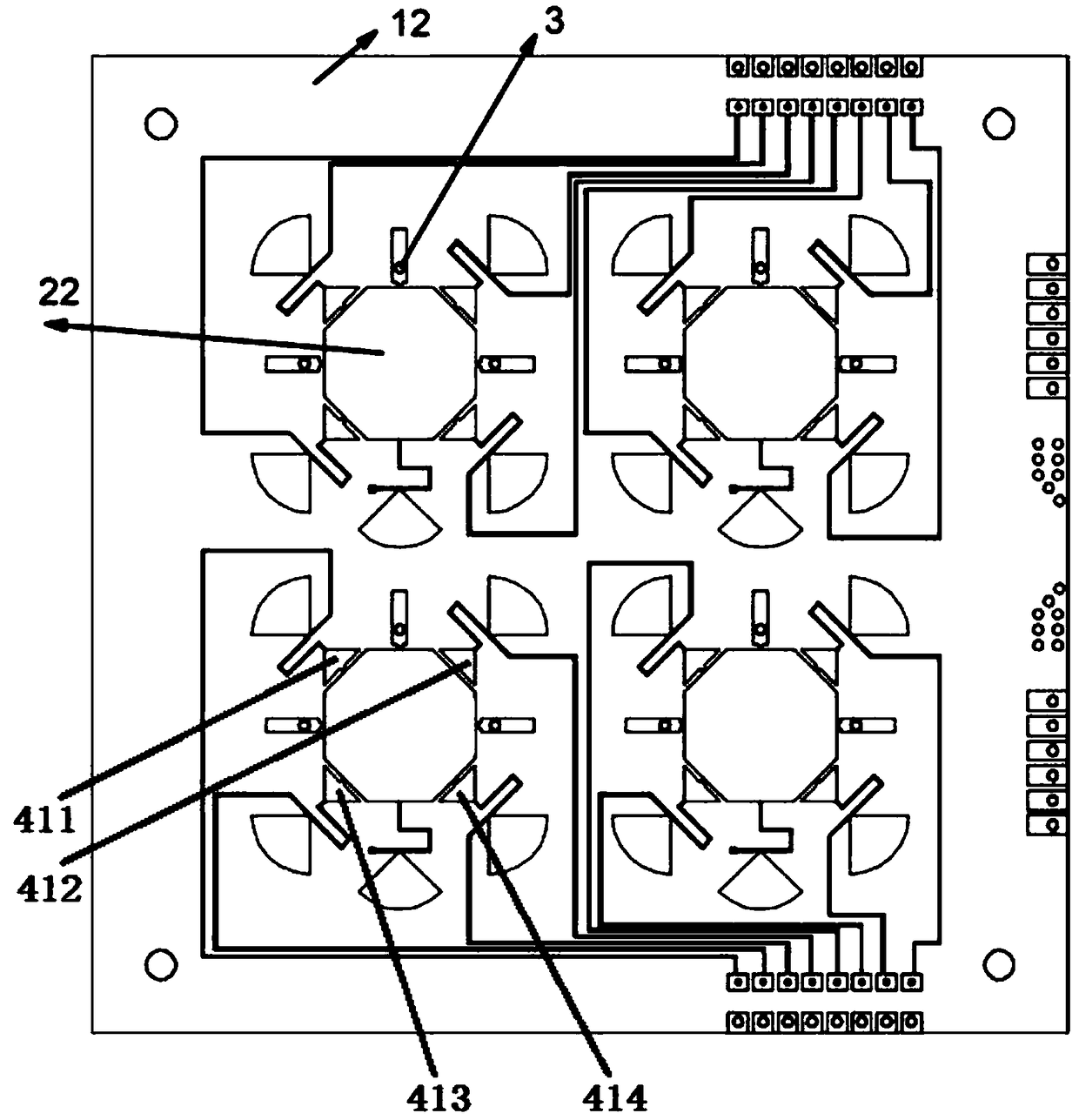
[0024] This specific embodiment discloses a reconfigurable antenna with pattern and polarization, such as figure 1 As shown, it includes four antenna units and four switches corresponding to the antenna units. Each antenna unit has two pairs of controllable perturbation parts, and the two pairs of controllable perturbation parts are respectively corresponding to the switches of the antenna unit. Connected, the switch is used to control the state of the perturbation part to change the disturbance to the current. like image 3 As shown, taking the antenna unit in the lower left corner as an example, the two pairs of controllable perturbation parts include a first controllable perturbation part 411, a second controllable perturbation part 412, a third controllable perturbation part 413 and The fourth controllable perturbation part 414, the first co...


PUM


Abstract

The invention discloses a directional diagram and polarization reconstructable antenna which comprises four antenna units and four switches that are in one-to-one correspondence with the antenna units. Each antenna unit has two pairs of controllable perturbation parts. The two pairs of controllable perturbation parts are respectively connected with the switch which corresponds with the antenna unit. The switch is used for controlling the state of the perturbation part, thereby changing disturbance to the current. Each antenna unit comprises three feeding ports. The feeding ports of each antenna unit are connected with the switch which corresponds with the antenna unit with the feeding ports by feeding probes through transmission wires. The transmission wire is divided into two parts by a first equal-phase equal-amplitude power divider. Each part is divided into two parts by a second equal-phase equal-amplitude power divider. The finally divided four parts are connected with four switches. The directional diagram and polarization reconstructable antenna can realize the directional diagrams in different directions and furthermore can realize left-hand circular polarization and right-hand polarization.

Description

technical field [0001] The invention relates to antenna technology, in particular to a reconfigurable antenna with pattern and polarization. Background technique [0002] The rapid development of wireless communication technology puts forward higher requirements for the system. The traditional single-function antenna cannot meet the current needs well, and has become a bottleneck restricting the development of system performance. The proposal and development of reconfigurable antennas provide a good solution to these problems. Reconfigurable antennas can increase system capacity through frequency multiplexing, and can solve the problem of polarization mismatch in communication, thereby improving communication quality. [0003] Since the modern single-layer PCB technology is very mature, the processing accuracy is also guaranteed in the not very high frequency band. At the same time, the processed products can have the characteristics of low profile, small volume and high in...

Claims


Application Information

Patent Timeline
IPC IPC(8): H01Q21/24H01Q21/29H01Q21/00H01Q3/24H01Q1/38H01Q1/50
CPCH01Q1/38H01Q1/50H01Q3/247H01Q21/0006H01Q21/245H01Q21/293
Inventor 郝张成胡俊
Owner SOUTHEAST UNIV
Learn More