Temperature control method for electric heating pad

A temperature control method and electric heating pad technology, which is applied in the direction of temperature control using electric methods, electric heating devices, ohmic resistance heating parts, etc., can solve the problems of electric heating pads or blankets on fire, complicated internal wiring, and reliability discounts.

Active Publication Date: 2018-12-07
滁州国康医疗仪器有限公司
View PDF6 Cites 2 Cited by
  • Summary
  • Abstract
  • Description
  • Claims
  • Application Information

AI Technical Summary

Problems solved by technology

However, a one-time thermal fuse can only collect the temperature of one point and cannot reflect the temperature of the entire mat, so the reliability is greatly reduced. If many disposable thermal fuses are installed in the mat, the reliability will of course be improved, but the production cost The height and the internal wiring become complicated, and it is difficult to realize in the process
Heating pads or blankets are bound to cause fires when NTC temperature sensors and / or one-time thermal fuses fail or are not set

Method used


Image

  • Temperature control method for electric heating pad
  • Temperature control method for electric heating pad

Examples


Embodiment 1

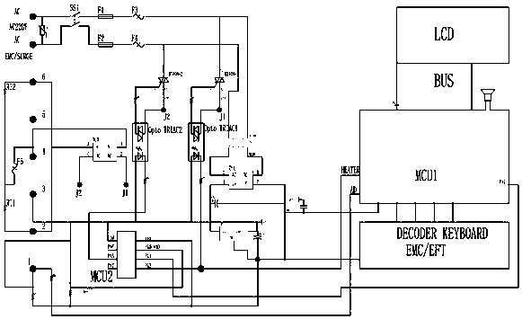
[0029] For the control device adopted in the temperature control method of the electric heating pad in this embodiment, see figure 1 As shown, including the power supply for the heating wire (or wire) in the electric heating pad, the electric heating pad has a one-time thermal fuse F5. The power supply is connected to the control device by the mains 220V and then transformed and rectified to form a power supply output. The first temperature sensor ResThermal-1 and the first temperature control processor MCU1 are used to measure the real-time temperature of the electric heating pad. The first electronic switch BTA08-1 and the second electronic switch BTA08-2 are arranged between the power supply and the heating line. An AND gate is formed between the electronic switch BTA08-1 and the second electronic switch BTA08-2. It also includes the second temperature control processor MCU2, and the keyboard decoder through DECODER KEYBOARD. The input terminal of the first electronic swi...

Embodiment 2

[0049] The temperature control method of the electric heating pad in this embodiment is an improvement on the basis of Embodiment 1, except that it is the same as Embodiment 1. The difference is:

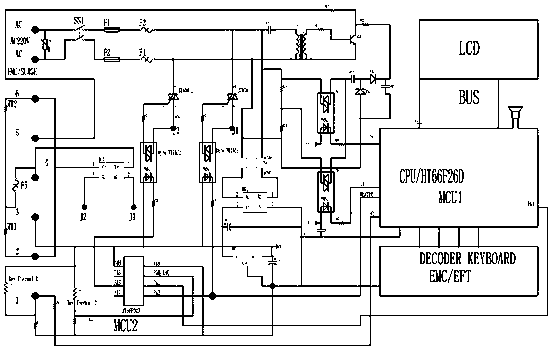
[0050] 1) if figure 2 As shown, the second temperature sensor ResThermal-2 for measuring the real-time temperature of the environment is added, and the limit value of the ambient temperature is set in the second temperature control processor MCU2, and the real-time temperature of the environment is measured at the same time. When the real-time temperature of the environment is greater than or equal to the limit value of the ambient temperature , control the electric heating pad to stop powering on, the ambient temperature limit in this embodiment is 35°C, the ambient temperature limit is selected according to human experience, and is not limited to 35°C;

[0051] 2) if figure 2 As shown, a negative potential generating unit is added. The mains 220V is output to the negative pote...


PUM


Abstract

The invention relates to a temperature control method for an electric heating pad, and belongs to the technical field of electric heating control. The method comprises 1) setting a constant temperature value and a fixed time; 2) measuring the real-time temperature value of the electric heating pad and comparing the same with the constant temperature value; 3) when the real-time temperature value is less than the constant temperature value, continuously powering the electric heating pad the fixed time by using a pulse signal having a first duty cycle of 100%; 4) when the fixed time expires, pulse-powering the electric heating pad by a pulse signal having a second duty cycle less than 100%; 5)when the real-time temperature value is greater than or equal to the constant temperature value, stopping powering the electric heating pad; and 6) when the real-time temperature measurement and/or the temperature fuse of the electric heating pad fail(s), pulse-powering the electric heating pad by the pulse signal having the second duty cycle. The method, even if the temperature sensor and the temperature fuse of the existing electric heating pad fail, can maintain the temperature of the electric heating pad at a temperature not over than a safe maximum temperature, so as to thoroughly ensure that the electric heating pad does not catch fire.

Description

technical field [0001] The invention relates to a temperature control method of an electric heating blanket or an electric heating pad, belonging to the technical field of electric heating control. Background technique [0002] Pads or blankets for electric heating or physiotherapy are widely used in people's daily life. This kind of electric heating sleeping pad is generally a constant temperature control type, and the control constant temperature value is set between 25°C and 50°C. In this temperature range, the temperature sensor installed in the pad or blanket is used to sample the heating temperature in real time, and the sampled value is compared with the set temperature value to realize automatic temperature adjustment, so as to achieve the purpose of constant temperature. This temperature control is the mode commonly used at present, and a point sampling NTC temperature sensor and a disposable temperature-limiting temperature fuse are generally installed in the pad ...

Claims


Application Information

Patent Timeline
Patent Type & Authority Applications(China)
IPC IPC(8): H05B1/02H05B3/02G05D23/19
CPCG05D23/19H05B1/02H05B1/0252H05B3/02
Inventor 张慧兵
Owner 滁州国康医疗仪器有限公司
Why Eureka
Try Eureka