Direct injection system in engine cavity
A technology for engines and engine cylinder heads, which is applied in the manufacture of engine combustion systems and in the field of engines, which can solve the problems of incomplete combustion of mixture gas, consumption of oxygen molecules, and slow combustion speed, so as to improve ignition combustion efficiency, complete combustion, and prolong life. Effect
- Summary
- Abstract
- Description
- Claims
- Application Information
AI Technical Summary
Problems solved by technology
Method used
Image
Examples
Embodiment 1
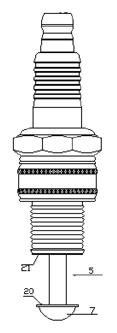
[0032] Example 1: Combining figure 1 , The flame nozzle in the figure includes a shell, which is equipped with a porcelain insulator, a double-headed screw with a wiring nut inside the porcelain insulator, a conductor glass sealant, and a center electrode extending from the porcelain insulator at one end, and a center electrode end protruding from the porcelain insulator The part is welded with the flame cap 7, wherein the flame cap 7 is a hemispherical structure, and the vertical distance between the hemispherical plane 20 and the end face 21 of the shell 3 is greater than 8 millimeters, which is 10 millimeters in this example. Wherein the central electrode only protrudes from the porcelain insulator at the part welded with the flame cap 7, and the other parts of the central electrode are wrapped by the porcelain insulator. Flame cap 7 can be the combination of hemispherical shown in the figure and a platform, also can be exactly hemispherical, also can be structures such as ...
Embodiment 2
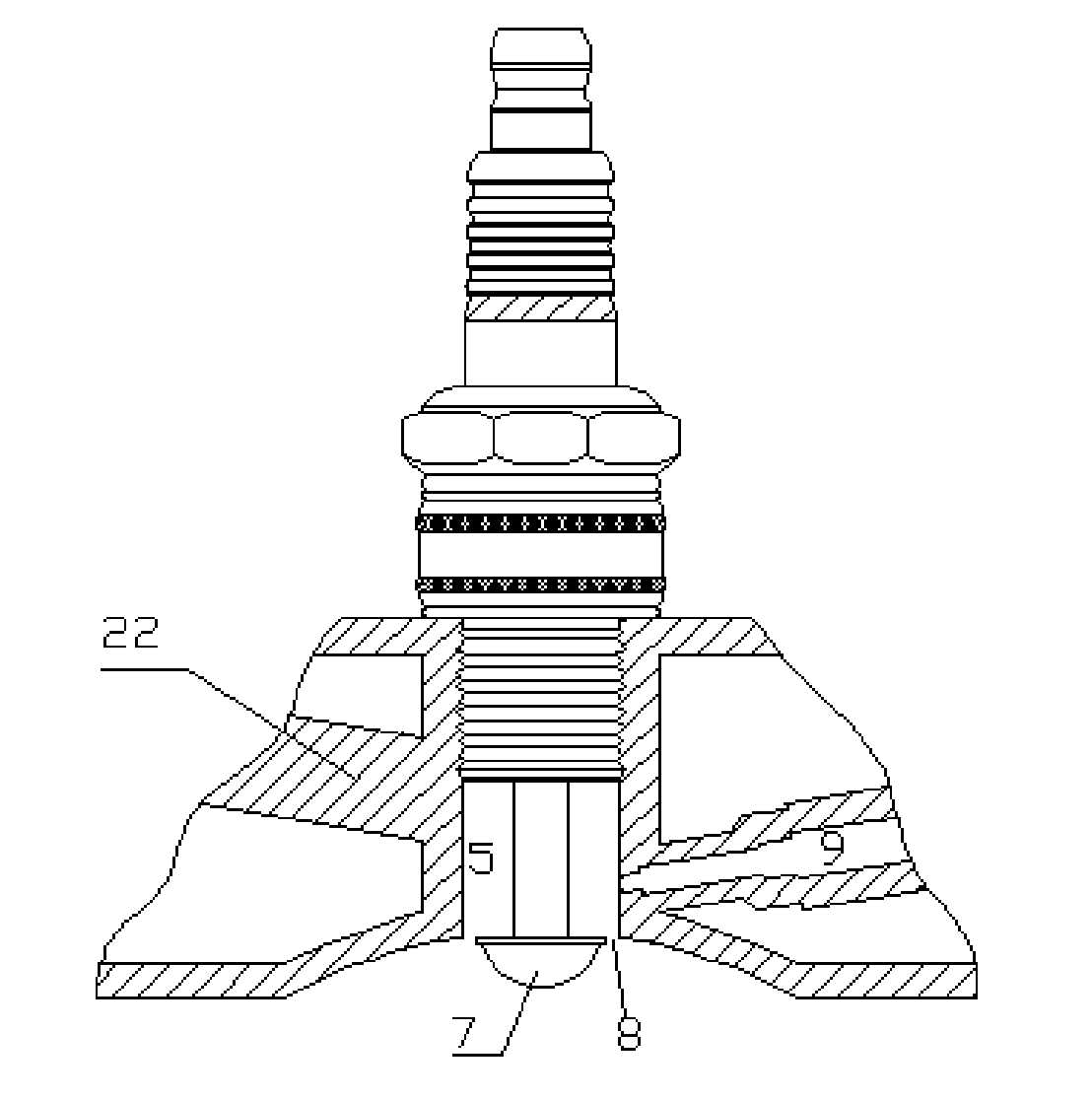
[0034] Example 2: Combining figure 2 , using the flame nozzle of the present invention on a gasoline engine, figure 2 The fuel nozzle 9 in the fuel injection chamber is in the thermal volume flame injection chamber, and it can be seen from the installation position of the gasoline fuel injection nozzle that the flame injection combustion system is composed of the main components with the flame injection nozzle as the center. The central part of the flame nozzle is designed to be installed in a small chamber in the heat volume fire chamber and exposed to the space. The entire heat volume fire chamber absorbs a large amount of heat energy, absorbing more heat and dissipating less heat to form a high-temperature hot zone, waiting for the fuel injector When the fuel is injected into the "high-temperature hot chamber" formed by the center of the flame nozzle and the cylinder head, the temperature of the fuel will suddenly rise in the hot area, and the heated fuel will become atom...
Embodiment 3
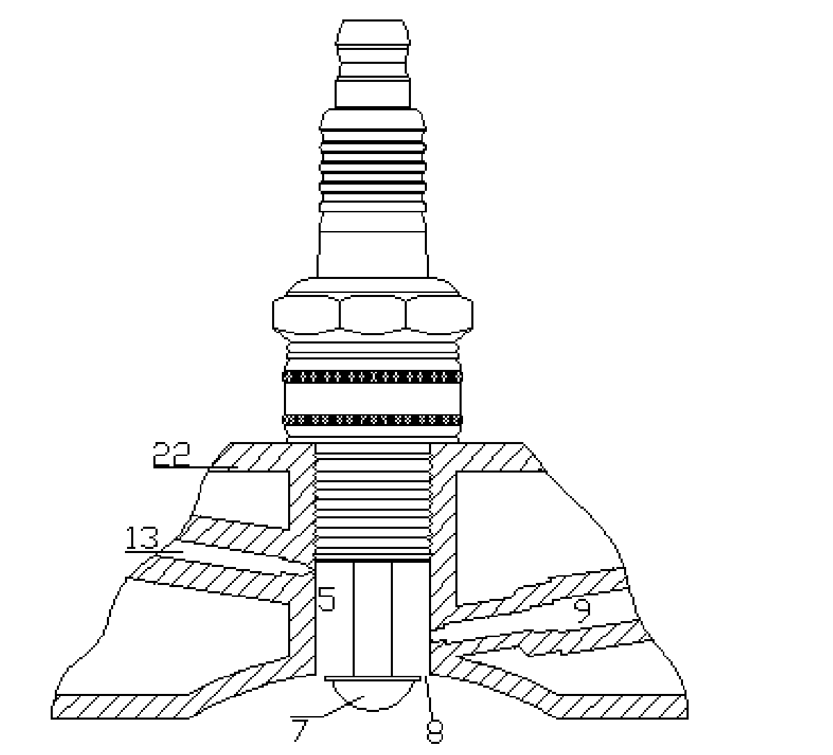
[0035] Example 3: Binding image 3 , same as embodiment 1, 2, but also have a gas spout 13 in the thermal volume flame injection chamber, the gas spout 13 can be the air spout, and the air can inject after pressurizing by the pressurizing device, the gas spout 13 can also be used as other For gas or fuel nozzles. The two nozzles have different functions in the engine. In this example: one nozzle is to inject high-pressure air to prevent the lack of oxygen molecules during high temperature and high pressure. The second injection is to inject fuel oil, which mixes high-pressure air and utilizes electric sparks to eject flames from the ignition gap and enter the combustion chamber. Gasoline nozzle 9. Gasoline is sprayed into the high-temperature small chamber. The high temperature of the central ceramic column and the flame cap heats and atomizes it. The atomized gasoline waits for the sharp corners of the edge of the flame cap and the edge of the inner hole of the cylinder head...
PUM
 Abstract
Description
Claims
Application Information
 - R&D
- Intellectual Property
- Life Sciences
- Materials
- Tech Scout
- Unparalleled Data Quality
- Higher Quality Content
- 60% Fewer Hallucinations
Browse by: Latest US Patents, China's latest patents, Technical Efficacy Thesaurus, Application Domain, Technology Topic, Popular Technical Reports.
© 2025 PatSnap. All rights reserved.Legal|Privacy policy|Modern Slavery Act Transparency Statement|Sitemap|About US| Contact US: help@patsnap.com


