Device with Trace Emission for Treatment of Exhaust Gas

a technology of trace emission and exhaust gas, which is applied in the direction of combustion types, separation processes, lighting and heating apparatuses, etc., can solve the problems of inability to perform the intended function, failure of ternary catalytic clarifiers, and secondary pollution, and achieves reduced pollution of exhaust gas, high speed, and strong rolling

Inactive Publication Date: 2008-07-31
ZHANG YUGUANG +1
View PDF24 Cites 2 Cited by
  • Summary
  • Abstract
  • Description
  • Claims
  • Application Information

AI Technical Summary

Benefits of technology

[0012]With this kind of configuration, the Device receives exhaust gas through its inlet with certain pressure, the exhaust gas enters into the exchange section and jets inwards. This jetting gas causes very strong entrainment effect and makes chamber become vacuum and air with oxygen being sucked into the chamber from atmosphere via the through opening to outside atmosphere. Combustible gas in this mixed gas with high pressure is burned furiously in the next gas chamber and combustible and harmful substances are decomposed in burning. The left exhaust gas is transferred into next exchange section. On entering next exchange section, exhaust gas revolves with high speed because of negative pressure in the gas chamber and the feedback effect of holes with negative pressure. The negative energy produced by the negative pressure and the working energy of the exhaust gas are balanced out each other and very strong rolling is resulted in. This causes heavy collisions and momentum transfer, i.e. “black hole” of gas. The higher the negative pressure is, the more exhaust gas is consumed, and trace amount of remaining not-consumed gas will be emitted via exhaust pipe. In this way, pollution of exhaust gas will be reduced significantly. The higher negative pressure is, the more gas is consumed. In this way, the exhaust gas will be treated and only trace emission, even no emission, will be resulted.

Problems solved by technology

Some techniques are based on combination of fuel and batteries to reduce emission and pollution, but techniques for disposal of used batteries are not in mature state and secondary pollution may be resulted.
In case any failure such as any damage of the oxygen sensor, control switch and / or air adding valve in electrical ejection device, it will cause the ternary catalytic clarifier become failure and cannot perform its intended function.
In addition, the alveolate structure of the ternary catalytic clarifier is easy to be clogged and saturated, and as result, loses its clarification ability.
These results in frequent replacement of clarifier and the operation cost will be increased (Generally, its normal operation period is limited within 90 days).
The ternary catalytic clarifier can play its role to reduce pollution from tail gas of motor vehicles only; it cannot eliminate the tail gas.

Method used


Image

  • Device with Trace Emission for Treatment of Exhaust Gas
  • Device with Trace Emission for Treatment of Exhaust Gas
  • Device with Trace Emission for Treatment of Exhaust Gas

Examples


Embodiment Construction

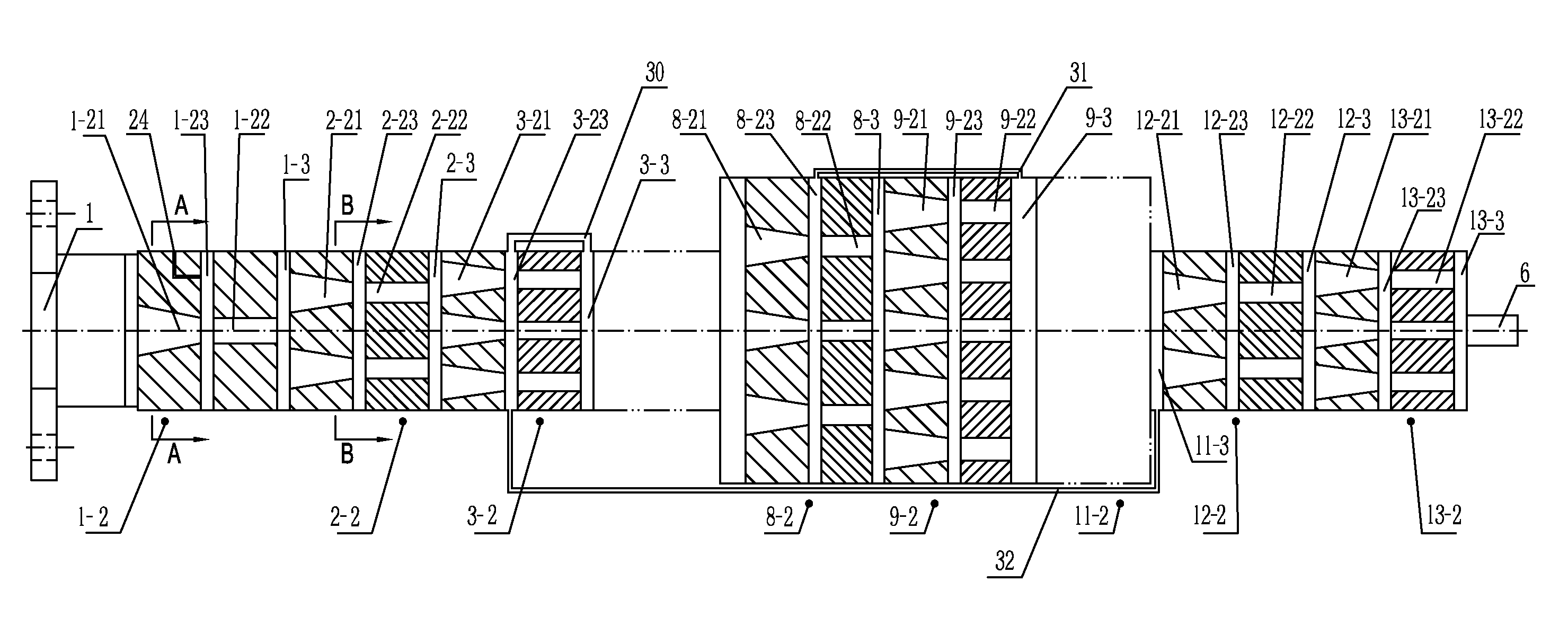
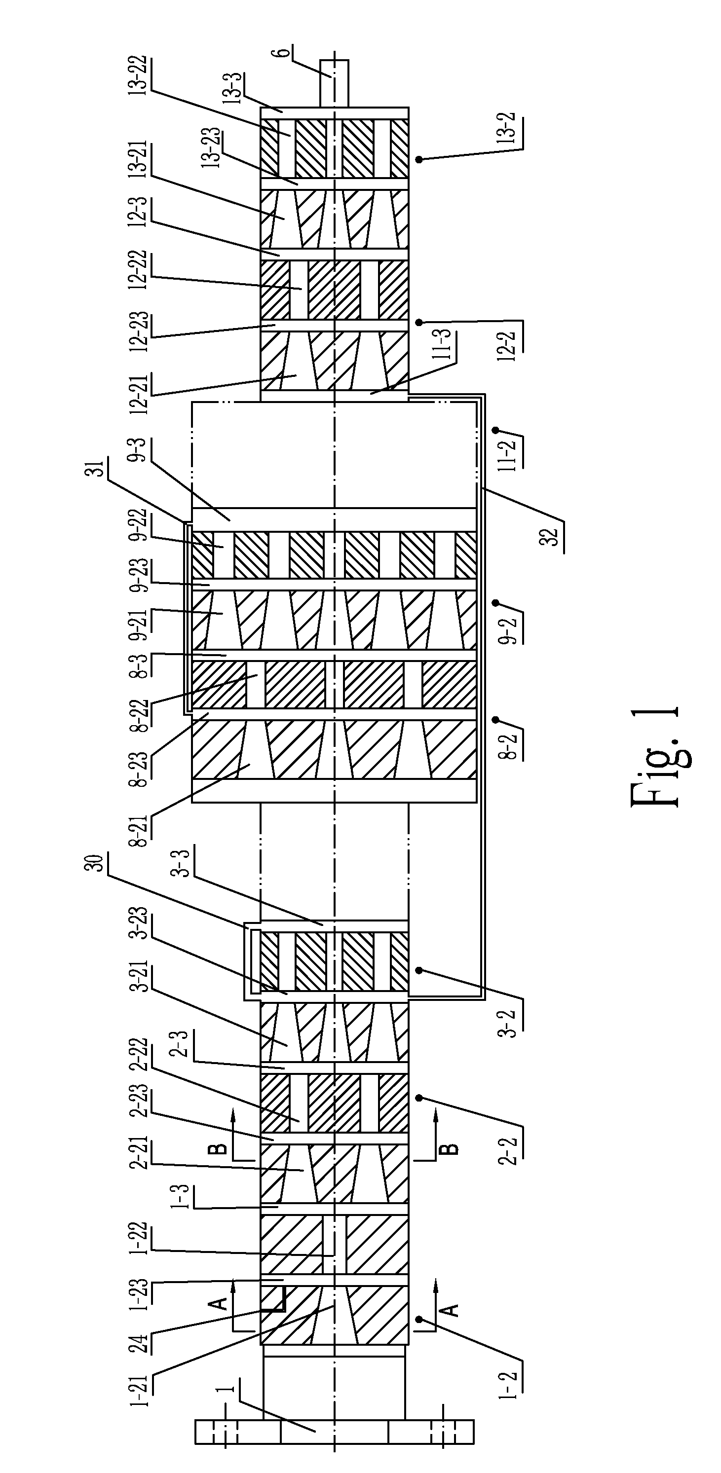
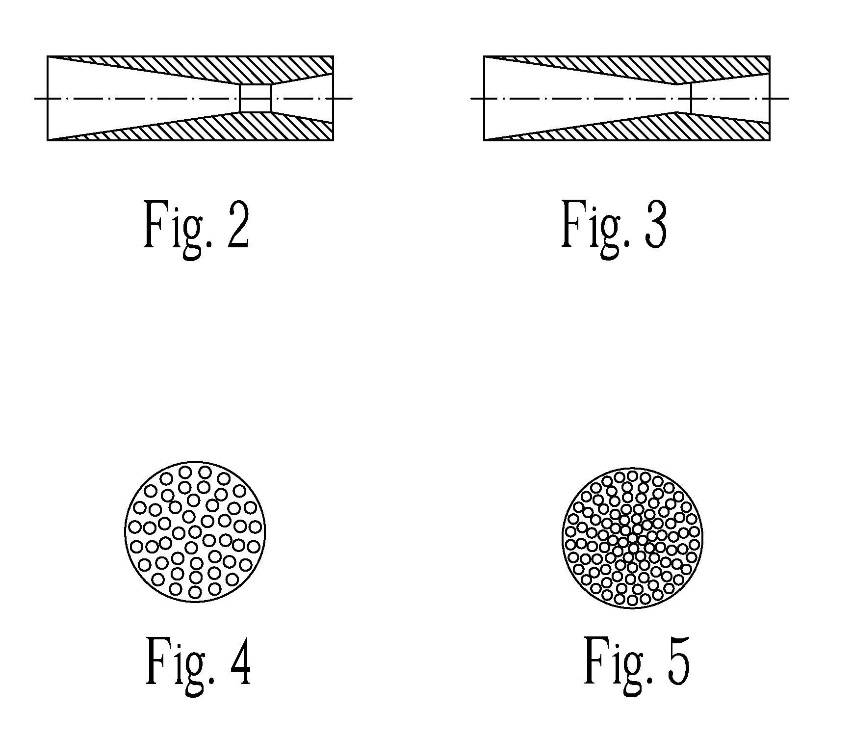
[0019]A device with trace emission for treatment of exhaust gas is shown in FIG. 1˜5. It is a vessel with openings only as inlet 1. At least thirteen gas exchange sections in sequence are provided inside the vessel after the inlet 1 of exhaust gas. Each gas exchange section 1-2, 2-2, - - - 13-2 is provided with a means with jet holes that has a plurality of jet holes 1-21, 2-21 - - - 13-21 and a means with diffusion holes that has a plurality of diffusion holes 1-22, 2-22, - - - 13-22 corresponding to the jet holes. Gas exchange chambers 1-23, 2-23 - - - 13-23 are provided between the means for jet holes and the means for diffusion holes correspondingly, connecting to both of them. A through opening 24 leading to outside atmosphere area is provided at the gas exchange chambers 1-23 of the first exchange section 1-2. Gas mixture chambers 1-3, 2-3 - - - 13-3 are provided at each connection part between two sequential gas exchange sections 1-2, 2-2 - - - 13-2, connecting the two neighb...


PUM


Abstract

This invention relates to a kind of devices with trace emission resulted for treatment of exhaust gas. The device comprises a vessel having only one opening that serves as inlet. At least two gas exchange sections in sequence are provided inside the vessel after inlet of exhaust gas, between two gas exchange sections there is a gas mixture chamber at their connection part. The gas exchange chamber at first gas exchange section has a through opening leading to outside atmosphere area. With this configuration, on entering into the gas exchange section, exhaust gas will be ejected inwards and causes very strong entrainment, which makes the gas chamber become vacuum and sucks air with oxygen from atmosphere into gas chamber via the through opening to atmosphere. Formed high-pressure gas is burned furiously with combustible gas in the gas chamber at next stage, and the remaining exhaust gas is transferred into next gas exchange section with very high-speed revolution occurring on exhaust gas and momentum transfer. The higher negative pressure is, the more gas is consumed. In this way, the exhaust gas will be treated and only trace emission, even no emission, will be resulted.

Description

CROSS REFERENCE TO RELATED PATENT APPLICATION [0001]This application claims the priority of the Chinese patent application No. 200710006461.X with a filing date of Jan. 30, 2007.FIELD OF THE INVENTION [0002]This Invention relates to devices for controlling pollution of exhaust gas, especially a kind of devices with trace emission for treatment of exhaust gas.BACKGROUND OF THE INVENTION [0003]There are many existing arts for controlling pollution of exhaust gas, for example, treatment of tail gas for motor vehicles and etc. Some techniques are based on combination of fuel and batteries to reduce emission and pollution, but techniques for disposal of used batteries are not in mature state and secondary pollution may be resulted. Some techniques are based on electrical ejection in conjunction with ternary catalytic clarifier. The China Government is promoting this technique energetically for controlling tail gas of motor vehicles.[0004]The ternary catalytic clarifier is actually an ext...

Claims


Application Information

Patent Timeline
Patent Type & Authority Applications(United States)
IPC IPC(8): F01N3/10F01N13/02F01N13/08
CPCF23C99/00F23G7/06F23D99/00B01D53/005B01D2258/01B01D53/92F01N3/34F01N13/00F01N13/02F01N13/08
Inventor ZHANG, YUGUANG
Owner ZHANG YUGUANG
Why Eureka
Try Eureka