BGA ball planting device and method

A technology of planting balls and solder balls, which is applied to the assembly of printed circuits with electrical components, electrical components, and printed circuit manufacturing. It can solve the problems of high BGA scrap rate, increase BGA cycle, and high recycling cost, so as to reduce costs and scrap rates. , speed up the effect of recycling

Inactive Publication Date: 2018-12-07
ZHENGZHOU YUNHAI INFORMATION TECH CO LTD
View PDF4 Cites 4 Cited by
  • Summary
  • Abstract
  • Description
  • Claims
  • Application Information

AI Technical Summary

Problems solved by technology

[0003] The main technology of BGA recycling at this stage is to return BGA to the original factory for ball planting machine reprocessing. This method not only wastes costs, but also increases the cycle of BGA reuse. It usually takes one to two months or even longer. Quickly recycle BGA, resulting in high BGA scrap rate and high recycling cost

Method used


Image

  • BGA ball planting device and method
  • BGA ball planting device and method
  • BGA ball planting device and method

Examples


Embodiment 1

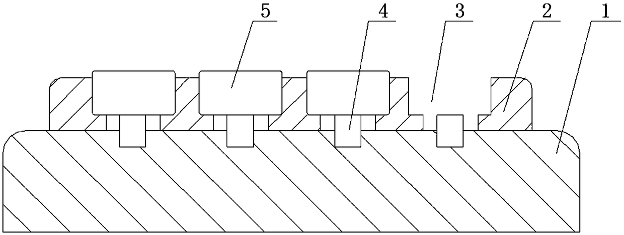
[0031] A BGA ball planting device, comprising a printing machine and a placement machine, the printing machine is provided with a printing fixture, the printing fixture includes a supporting base 1, and the supporting base 1 is provided with a support carrier 2, the The support carrier 2 is connected with the supporting base 1, and the support carrier 2 is provided with a groove 3, and the groove 3 is provided with a plurality of, and the cross-sectional shape of the groove 3 in the vertical direction is an inverted convex shape . A suction nozzle 4 is provided inside the groove 3 , the lower end of the suction nozzle 4 is connected to the support base 1 , and the upper end of the suction nozzle 1 sucks the lower surface of the BGA 5 . Because the support carrier 2 is provided with a plurality of grooves 3, and the plurality of grooves 3 can place a plurality of BGAs 5, so the printing fixture can realize simultaneous printing of a plurality of BGAs 5 at one time, thereby incr...

Embodiment 2

[0040] A BGA ball planting device, comprising a printing machine and a ball planting jig two, the printing machine is provided with a printing jig, and the printing jig includes a support base 1, and the support base 1 is provided with a support carrier 2, The supporting carrier 2 is connected with the supporting base 1, the supporting carrier 2 is provided with grooves 3, and the grooves 3 are provided with a plurality, and the cross-sectional shape of the grooves 3 in the vertical direction is inverted. convex. A suction nozzle 4 is provided inside the groove 3 , the lower end of the suction nozzle 4 is connected to the support base 1 , and the upper end of the suction nozzle 1 sucks the lower surface of the BGA 5 . Because the support carrier 2 is provided with a plurality of grooves 3, and the plurality of grooves 3 can place a plurality of BGAs 5, so the printing fixture can realize simultaneous printing of a plurality of BGAs 5 at one time, thereby increasing the printin...


PUM


Abstract

The invention discloses a BGA (Ball Grid Array) ball planting device and method, which belong to the technical field of BGA ball planting. The device comprises a printer and a laminator. The printer is provided with a printing fixture which includes a supporting base. The supporting base is provided with a supporting carrier which is connected with the supporting base. The supporting carrier is provided with multiple grooves, and the cross sections of the grooves in the vertical direction are in an inverted convex shape. The laminator comprises a ball planting fixture I which includes a suction nozzle II. The cross section of the suction nozzle II in the vertical direction is convex. The suction nozzle II is of a hollow structure inside, and is provided with multiple small holes in the lower surface thereof. The small holes are communicated with the hollow structure, and are evenly distributed on the lower surface of the suction nozzle. The method comprises the following steps: (1) tinremoving; (2) cleaning; (3) printing; (4) ball planting; and (5) reflow soldering. BGA components can be quickly recovered and utilized, the scrap rate of parts is reduced, and the effect of cost reducing is achieved.

Description

technical field [0001] The invention relates to the technical field of BGA ball planting, in particular to a BGA ball planting device and method. Background technique [0002] At present, SMT technology has developed to a fairly mature stage, and various electronic parts are widely used in electronic products. BGA is the most important and expensive electronic component in SMT parts. Its secondary recycling can greatly reduce product costs. [0003] The main technology of BGA recycling at this stage is to return BGA to the original factory for ball planting machine reprocessing. This method not only wastes costs, but also increases the cycle of BGA reuse. It usually takes one to two months or even longer. Rapid recycling of BGAs results in a high scrap rate of BGAs and high recycling costs. Contents of the invention [0004] Aiming at the above-mentioned deficiencies in the prior art, the present invention proposes a BGA ball planting device and method, which can realize ...

Claims


Application Information

Patent Timeline
Patent Type & Authority Applications(China)
IPC IPC(8): H05K3/34
CPCH05K3/341H05K3/3457
Inventor 郭秀云刘鹏
Owner ZHENGZHOU YUNHAI INFORMATION TECH CO LTD
Why Eureka
Try Eureka