Cutting fluid circulating device for numerical control machine tool and using method of cutting fluid circulating device

A technology of numerical control machine tools and circulation devices, which is applied in the direction of separation methods, chemical instruments and methods, metal processing machinery parts, etc., can solve the problems of unstable blowing direction, no design of drying structure, and weakened advantages, so as to improve secondary utilization efficiency, better drying effect, and increased dilution speed

Inactive Publication Date: 2020-05-12
HEZE UNIV
View PDF16 Cites 6 Cited by
  • Summary
  • Abstract
  • Description
  • Claims
  • Application Information

AI Technical Summary

Problems solved by technology

[0007] 1. The filter plate is fixed and there is no shaking structure. When the cutting fluid is filtered from the cutting chips, the cutting fluid contaminated on the cutting chips cannot be filtered out effectively, and more cutting fluid will remain on the surface of the cutting chips, so It is easy to reduce the utilization rate of cutting fluid, which is not conducive to its recycling
[0008] 2. There is no drying structure in the collection box. After the cutting chips and cutting fluid are separated into the collection box, they cannot be recycled quickly, thus reducing the secondary utilization rate of cutting chips and easily causing waste of resources.
[0009] 3. The effect of drying the residual cutting fluid on the surface of the cutting chips by airflow is weak, and the blowing direction of the airflow is adjusted by the roller driving the ball is not stable, and the drying range is limited, so it is impossible to dry all in the collection box in a timely and effective manner. Cuttings
[0010] 4. There is no stirring mechanism in the recovery box, the cutting fluid cannot be diluted quickly, so the circulation speed will slow down, and the advantages of recycling will be weakened

Method used


Image

  • Cutting fluid circulating device for numerical control machine tool and using method of cutting fluid circulating device
  • Cutting fluid circulating device for numerical control machine tool and using method of cutting fluid circulating device
  • Cutting fluid circulating device for numerical control machine tool and using method of cutting fluid circulating device

Examples


Embodiment Construction

[0043] The technical solution of the present invention will be further described below in conjunction with the accompanying drawings and through specific implementation methods.

[0044] Wherein, the accompanying drawings are only for illustrative purposes, showing only schematic diagrams, rather than physical drawings, and should not be construed as limitations on this patent; in order to better illustrate the embodiments of the present invention, some parts of the accompanying drawings will be omitted, Enlarged or reduced, does not represent actual product size.

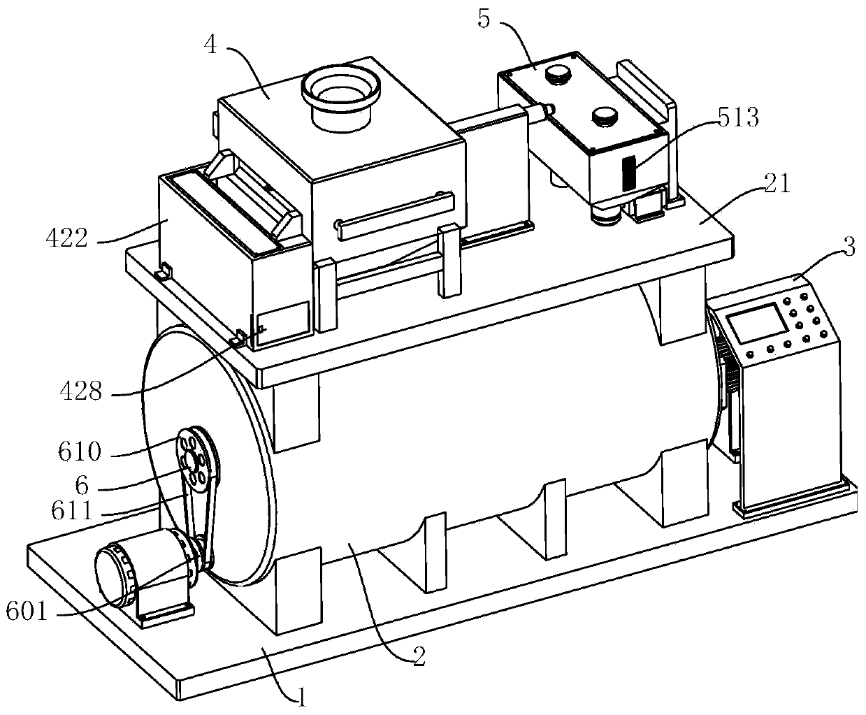
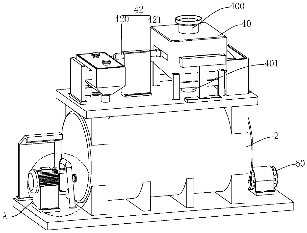
[0045] refer to Figure 1 to Figure 9 The shown chip liquid circulation device for CNC machine tools includes a base 1 and a recovery bucket 2, the base 1 is arranged horizontally, the recovery bucket 2 is fixed on the base 1, and the inner wall of the recovery bucket 2 is fixed with The liquid level sensor 20, the top outer wall of the recovery bucket 2 is fixed with a horizontal plate 21, and also includes a con...


PUM


Abstract

The invention relates to the technical field of numerical control machine tool machining, in particular to a cutting fluid circulating device for a numerical control machine tool and a using method ofthe cutting fluid circulating device. The cutting fluid circulating device comprises a base and a recycling barrel, wherein a liquid level sensor is fixedly arranged on the inner wall of the recycling barrel; and the cutting fluid circulating device further comprises a controller, a filtering mechanism, a proportioning mechanism and a stirring mechanism, wherein the filtering mechanism comprisesa filtering box, a shaking assembly and a pushing assembly, the proportioning mechanism comprises a storage box and a proportioning assembly, the stirring mechanism comprises a driving motor, a rotating shaft and a stirring assembly, and the driving motor, the liquid level sensor, the shaking assembly, the pushing assembly and the proportioning assembly are all electrically connected with the controller. According to the cutting fluid circulating device for the numerical control machine tool and the using method of the cutting fluid circulating device, cutting fluid contaminated on cutting chips can be fully separated out, and more cutting fluid cannot be left on the surfaces of the cutting chips, so that the utilization rate of the cutting fluid is increased, and cyclic utilization of thecutting fluid is facilitated; and meanwhile, the cutting chips in a collecting box are dried in time, so that the cutting chips can be rapidly recycled.

Description

technical field [0001] The invention relates to the technical field of numerical control machine tools, in particular to a chip liquid circulation device for numerical control machine tools and a method for using the same. Background technique [0002] CNC machine tool is the abbreviation of numerical control machine tool, which is an automatic machine tool equipped with a program control system. The control system can logically process programs with control codes or other symbolic instructions, decode them, express them in coded numbers, and input them into the numerical control device through the information carrier. After calculation and processing, various control signals are sent by the numerical control device to control the movement of the machine tool, and the parts are automatically processed according to the shape and size required by the drawing. CNC machine tools solve complex, precise, small-batch, and multi-variety parts processing problems. It is a flexible, ...

Claims


Application Information

Patent Timeline
Patent Type & Authority Applications(China)
IPC IPC(8): B23Q11/12B01D33/03B01D33/80
CPCB01D33/03B01D33/801B23Q11/12
Inventor 田俊英孟云男
Owner HEZE UNIV
Why Eureka
Try Eureka