Puncture body surface location fence and use method thereof

A fence and body surface technology, which is applied in the field of medical devices, can solve the problems of inability to determine the cross-sectional plane and the inability to locate the body surface, etc., and achieve the effect of reducing puncture time, ensuring success rate, and improving puncture efficiency

Inactive Publication Date: 2018-12-11
杨会军 +1
View PDF0 Cites 3 Cited by
  • Summary
  • Abstract
  • Description
  • Claims
  • Application Information

AI Technical Summary

Problems solved by technology

However, there is no bed surface movement in DSA CT imaging, and there is no specific number of ordinary CT scanning bed movement, so the specific cross-sectional plane cannot be determined
Therefore, using ordinary fences, it is impossible to determine the cross-sectional plane and accurately locate the body surface

Method used


Image

  • Puncture body surface location fence and use method thereof
  • Puncture body surface location fence and use method thereof
  • Puncture body surface location fence and use method thereof

Examples


Embodiment 1

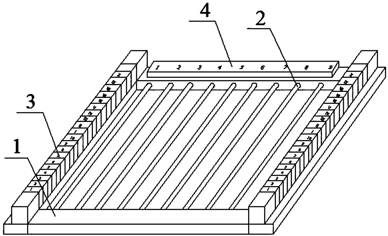
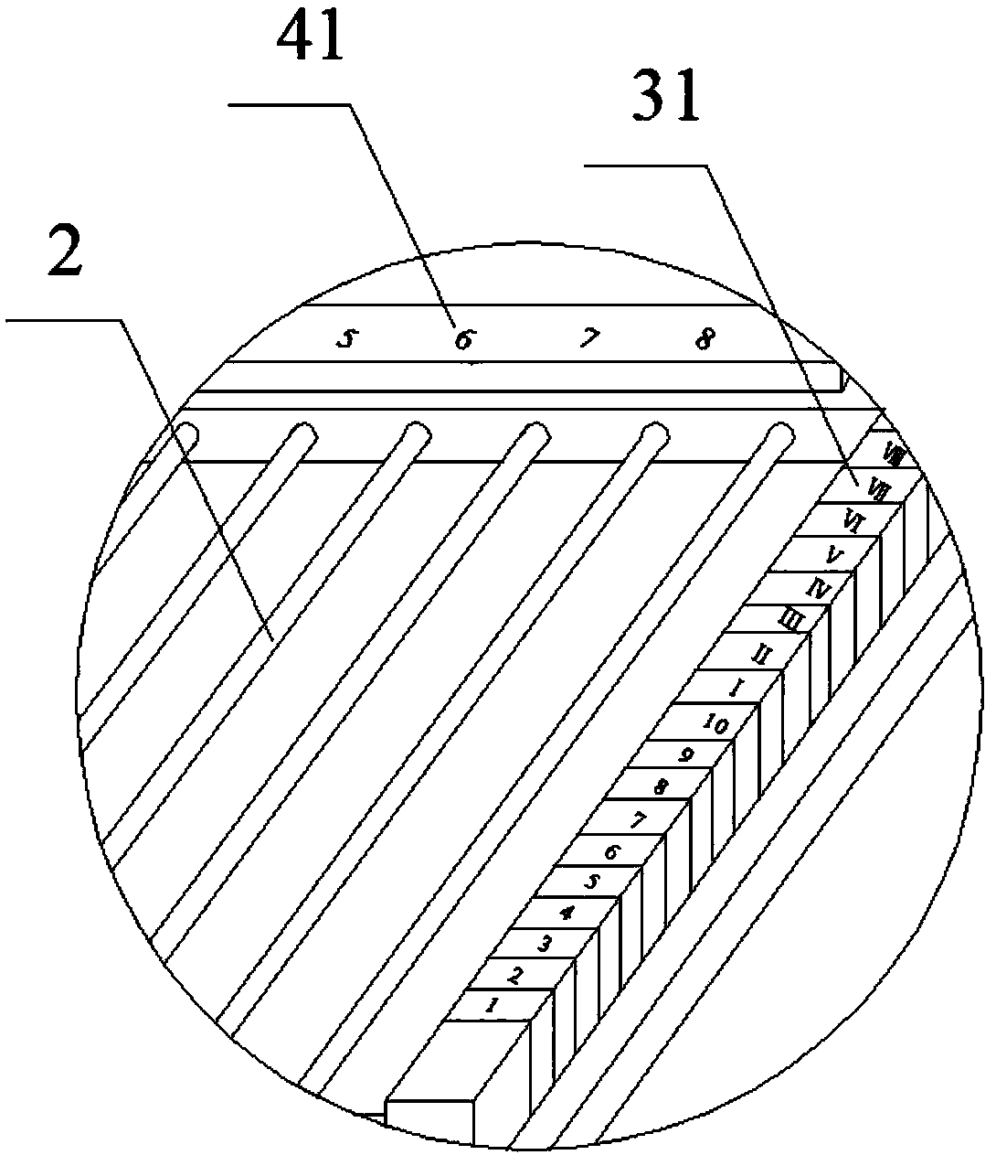
[0041] see figure 1 In this embodiment, a puncture body surface positioning fence is provided, including a fixed frame 1, a fence line 2 in the fixed frame 1, and a longitudinal positioning plate 3 and a lateral positioning plate 4 respectively located on the vertical side of the fixed frame 1, and the outer side of the fixed frame 1 A connecting piece is also provided, and the connecting piece can be an adhesive plaster.

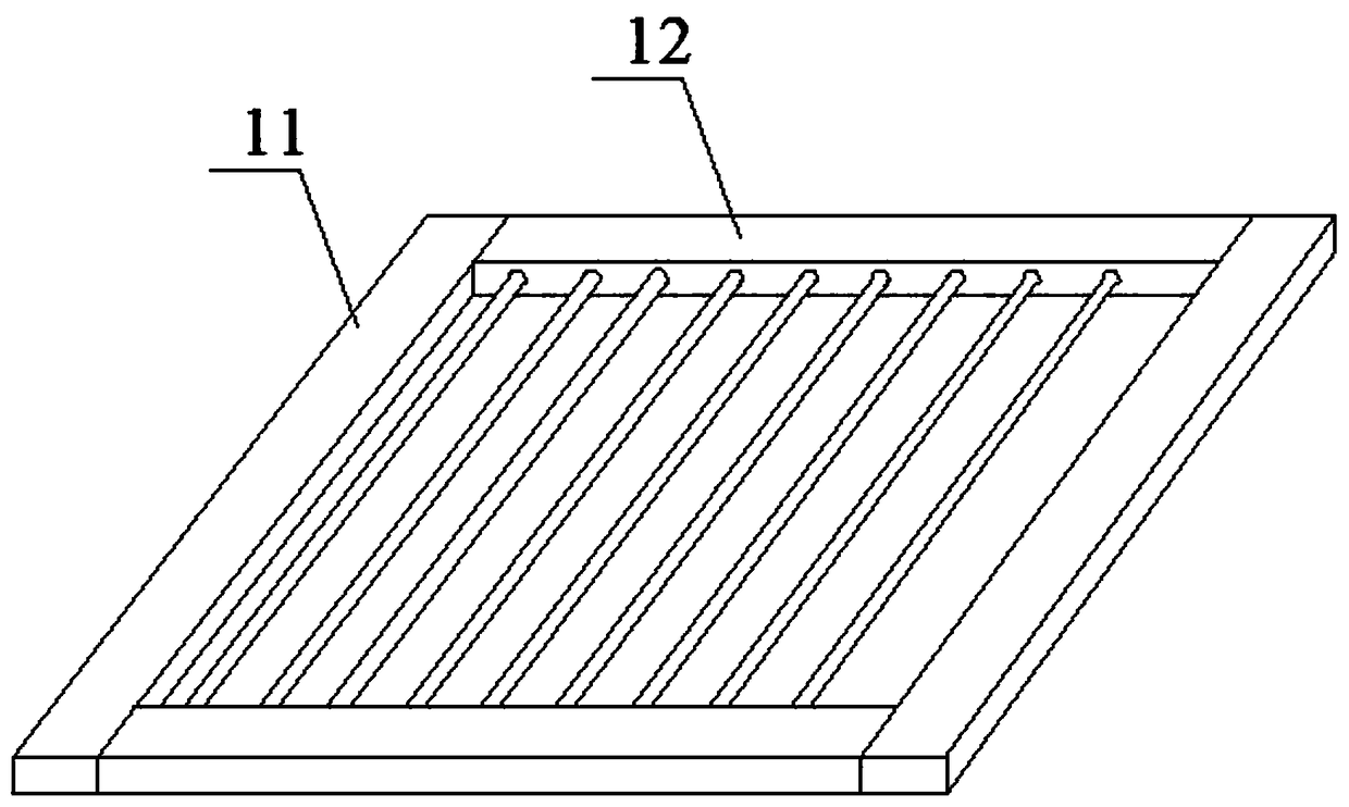
[0042] see image 3 , the structure of the fixed frame 1 and the fence line 2 is as follows: the fixed frame 1 is a rectangular structure, including two wide frame sides 11 and two long frame sides 12, several fence lines 2 are arranged in parallel with each other and at equal intervals, and the fence lines 2 simultaneously It is also parallel to the wide frame sides 11 and the inner sides of the two wide frame sides 11 are correspondingly fixed at both ends of the fence line 2 , and the fence line 2 is made of metal material.

[0043] The structure of th...

Embodiment 2

[0056] On the basis of Embodiment 1, the difference of Embodiment 2 lies in that several hollow grooves 311 are arranged at intervals in front and rear and do not communicate with each other.

[0057] Adopting such a structure is used to further improve the accuracy of the connection between the front and rear positioning blocks 31. At this time, on the CT imaging image obtained by scanning, there are two groups of identical longitudinal marks 312 on the left and right sides respectively. When the CT image scans When the vertical position is just at the junction of the two positioning blocks 31 , two spaced longitudinal marks 312 will be displayed on the left and right sides on the CT image, which means that the vertical position of the scan is at the junction of the two longitudinal marks 312 .


PUM


Abstract

The invention discloses a puncture body surface location fence and a use method thereof. The location fence comprises a fixing frame, a plurality of fence lines are arranged in the fixing frame alongthe width direction, a longitudinal location plate is arranged on wide frame edges of the fixing frame, is parallel to the fence lines and comprises a plurality of location blocks, a plurality of hollowed-out grooves are formed in the longitudinal location plate in a front and back penetrating manner and formed in the location blocks in a one-to-one corresponding manner, the hollowed-out grooves are perpendicular to the fence lines, the horizontal projections of the hollowed-out grooves are different from each other, the tops of the location blocks are provided with longitudinal markers in shapes corresponding to those of the hollowed-out grooves, and a transverse location plate is arranged on long frame edges of the fixing frame and provided with transverse markers. The use method includes the steps: (1) fixing the fixing frame to a body surface; (2) performing DSA (digital subtraction angiography) CT (computed tomography) imaging to obtain a CT image; (3) determining penetration points and the like. The puncture body surface location fence is high in accuracy and convenient to use.

Description

technical field [0001] The invention belongs to the technical field of medical devices, and in particular relates to a body surface puncture positioning fence and a method for using the same. Background technique [0002] When certain diseases occur inside the human body, in order to correctly diagnose the pathology and make the correct treatment, it is necessary to use puncture to biopsy the lesion, or to perform directional treatment through puncture, usually with the help of instruments such as CT scanning devices and DSA CT scans The equipment measures the position of the lesion and the positioning point of the skin and the depth of the puncture needle. First, the position of the lesion is measured on a certain cross-sectional plane of the human body, and the optimal needle insertion position and angle are selected in this plane. The three-dimensional conformation of the angle of the needle, the angle of the needle and the depth of the needle determine the precise positi...

Claims


Application Information

Patent Timeline
Patent Type & Authority Applications(China)
IPC IPC(8): A61B17/34A61B90/00
CPCA61B17/3403A61B90/39A61B2090/3966
Inventor 杨会军高斌
Owner 杨会军
Why Eureka
Try Eureka