Spraying equipment for color plate production

A technology of spraying equipment and color steel plate, which is applied in the direction of spray paint booth, spraying device, etc., can solve the problem of color steel plate shifting and other problems, achieve the effect of flexible use and faster drying speed

Inactive Publication Date: 2018-12-11
TIANJIN YIXUNYUAN METAL PROD CO LTD
View PDF0 Cites 0 Cited by
  • Summary
  • Abstract
  • Description
  • Claims
  • Application Information

AI Technical Summary

Problems solved by technology

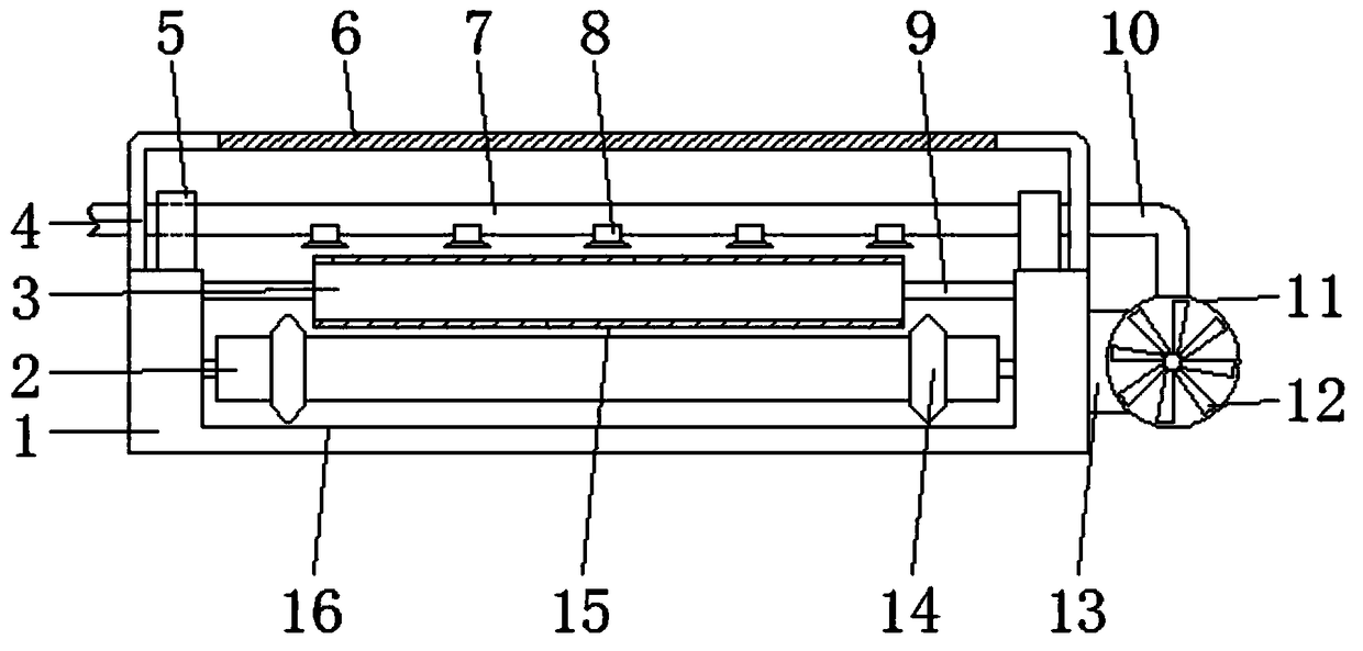
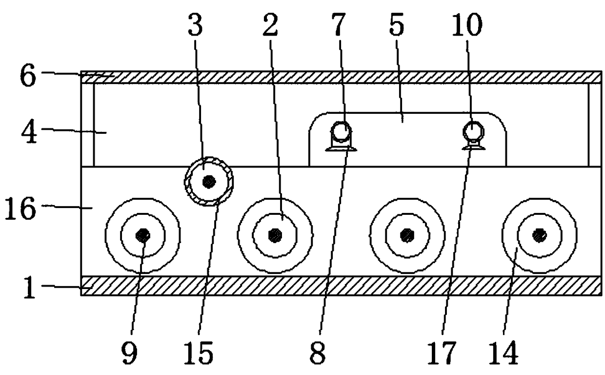
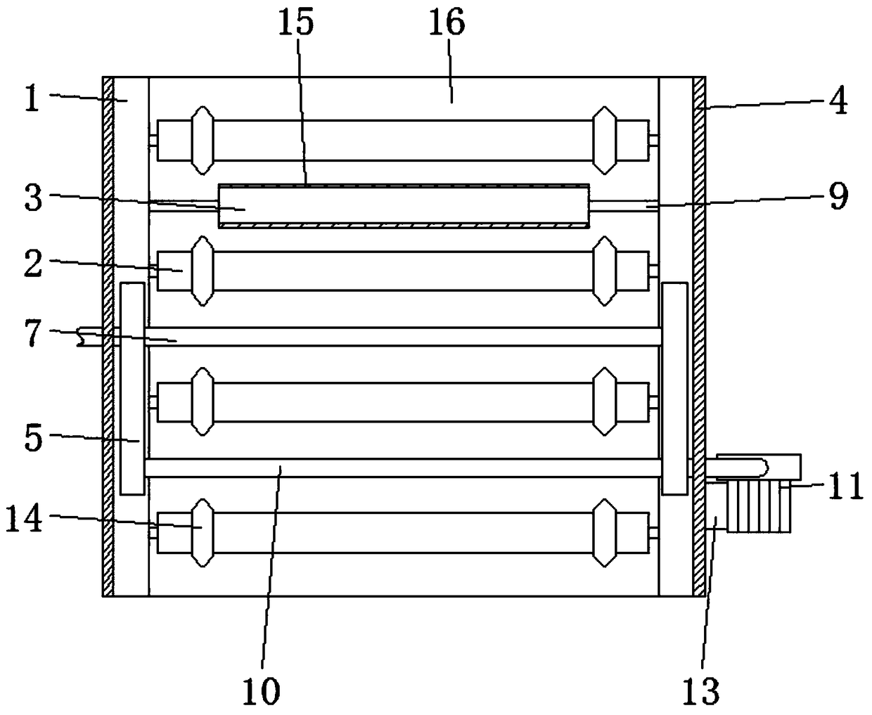
[0003] The purpose of the present invention is to provide a spraying equipment for the production of color steel plates, which has the advantage of limiting the movement of color steel plates, and solves the problem of deviation in the movement of color steel plates

Method used


Image

  • Spraying equipment for color plate production
  • Spraying equipment for color plate production
  • Spraying equipment for color plate production

Examples


Embodiment Construction

[0017] The following will clearly and completely describe the technical solutions in the embodiments of the present invention with reference to the accompanying drawings in the embodiments of the present invention. Obviously, the described embodiments are only some, not all, embodiments of the present invention. Based on the embodiments of the present invention, all other embodiments obtained by persons of ordinary skill in the art without making creative efforts belong to the protection scope of the present invention.

[0018] In the description of the present invention, it should be noted that the terms "upper", "lower", "inner", "outer", "front end", "rear end", "both ends", "one end", "another end" The orientation or positional relationship indicated by etc. is based on the orientation or positional relationship shown in the drawings, and is only for the convenience of describing the present invention and simplifying the description, rather than indicating or implying that ...


PUM


Abstract

The invention discloses spraying equipment for color plate production. The spraying equipment comprises a bottom plate, first roller columns, a protection cover, fixing blocks and a guiding groove. The guiding groove is formed in the upper surface of the bottom plate. The first roller columns distributed in parallel at equal intervals are movably arranged in the guiding groove. The outer walls ofthe two ends of the first roller columns are sleeved with symmetrically-distributed limiting wheels. Second roller columns are arranged above the first roller columns. The surfaces of the second roller columns are sleeved with rubber sleeves. The symmetrically-distributed fixing blocks are welded to the two ends of the upper surface of the bottom plate, and a paint spraying pipe and an air guidingpipe are inserted and connected in the fixing blocks. An installing block is fixed to the outer wall of one side of the bottom plate. An air pump is fixed to the outer wall of the side, deviating from the bottom plate, of the installing block. The protection cover is arranged on the upper surface of the bottom plate. A glass plate is embedded and installed in the upper surface of the protection cover. Through rotation of the limiting wheels in clamping grooves of a color plate, the effect of color plate limiting is achieved, and it is guaranteed that the situation of deflection of the color plate during moving is avoided.

Description

technical field [0001] The invention relates to the technical field of color steel plate production, in particular to a spraying equipment for color steel plate production. Background technique [0002] Color steel plate refers to color coated steel plate, which is a kind of steel plate with organic coating. Color steel plate is divided into veneer, color steel composite plate, floor bearing plate and so on. Widely used in walls and roofs of large public buildings, public workshops, prefabricated houses, and integrated houses. Before the color steel plate is painted, the surface of the color steel plate is bent to form grooves, and then the surface of the color steel plate is painted, and the phenomenon of deviation will occur during the movement of the color steel plate, thereby reducing the effect of painting, and there will be paint leakage, The phenomenon of excessive paint affects the quality of spray paint. Contents of the invention [0003] The object of the pres...

Claims


Application Information

Patent Timeline
IPC IPC(8): B05B13/02B05B16/40B05B16/20
CPCB05B13/0221B05B16/20B05B16/40B05B16/95
Inventor 许春雷
Owner TIANJIN YIXUNYUAN METAL PROD CO LTD
Why Eureka
Try Eureka