Clamping method and device for improving precision of circular trimmed shell type parts

A clamping device and a technology for parts are applied in the field of clamping methods and devices for machining and improving the accuracy of round edged shell parts, and achieve the effects of expanding the processing range, convenient manufacturing and simple structure.

Pending Publication Date: 2018-12-11
XIAN NORTH ELECTRO OPTIC TECH DEFENSE
View PDF6 Cites 2 Cited by
  • Summary
  • Abstract
  • Description
  • Claims
  • Application Information

AI Technical Summary

Problems solved by technology

The invention is used to improve the precision of the circular chamfered shell parts

Method used


Image

  • Clamping method and device for improving precision of circular trimmed shell type parts
  • Clamping method and device for improving precision of circular trimmed shell type parts
  • Clamping method and device for improving precision of circular trimmed shell type parts

Examples


Embodiment 1

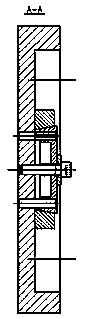
[0043] Such as figure 1 with figure 2 As shown in the figure, a clamping device for improving the accuracy of circular beveled shell parts includes a body 1, a surrounding inclined-plane pressing block 2 and a middle inclined-plane pressing block 3, the body 1 is provided with a cross-shaped groove, ten The 4 tops of the glyph grooves are all semicircular grooves 1-1; there are 4 oblique pressing blocks 2 around, as Figure 5 with 6 As shown, the surrounding inclined-plane pressing block 2 is a cylinder with a right-angled trapezoidal cross section, and the inclined surfaces of the four surrounding inclined-plane pressing blocks 2 are arranged in cross-shaped grooves, and each surrounding inclined-plane pressing block 2 corresponds to a semicircular groove 1 -1, and the length is less than the diameter of the semicircular groove 1-1; such as Figure 7 with8 As shown, the middle inclined-plane pressing block 3 is a square, and each of the four sides is provided with a wedge...

Embodiment 2

[0046] On the basis of Example 1, such as figure 1 As shown, the middle inclined-plane pressing block 3 is provided with a pressing plate 5 , and the screw 6 is threaded through the pressing plate 5 and the middle inclined-plane pressing block 3 and the body 1 .

[0047] Such as Figure 9 with 10 As shown, the pressure plate 5 is provided with an outwardly opening circular arc groove 5-1; the screw 6 transmits the pressure applied to the pressure plate 5 to the middle inclined plane pressing block 3 through the circular arc groove 5-1, and implements the Press tight. The use of circular arc grooves facilitates the adjustment of the force surface of the pressing plate on the middle inclined pressing block.

Embodiment 3

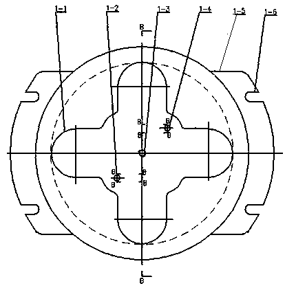
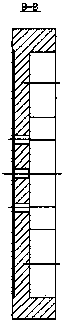
[0049] On the basis of embodiment 1 or embodiment 2, such as image 3 with Figure 4 As shown, the body 1 is disc-shaped, and fixed plates 1-5 are arranged symmetrically on both sides of the body 1, and two U-shaped grooves 1-6 that open outward are arranged on the fixed plates 1-5; The bottom surface of the body 1 is in contact with the machine tool plane, and the clamping device of the present invention is connected with the machine tool through the U-shaped groove 1-6 on the fixing plate 1-5, so that the clamping device of the present invention is fixed on the machine tool. A threaded hole 1-3 is provided at the center of the body 1, and a first positioning hole 1-2 and a second positioning hole 1-4 of the body are symmetrically arranged around the threaded hole 1-3. Such as Figure 7 with Figure 8 As shown, the middle inclined-plane pressing block 3 is provided with a square groove 3-5, and the opening direction of the square groove 3-5 is opposite to the body 1; a via...


PUM


Abstract

The invention relates to a clamping method and device for improving the precision of circular trimmed shell type parts. The clamping device comprises a body, four peripheral bevel pressing blocks anda middle bevel pressing block. The body is provided with cross grooves. Semi-circular grooves are formed in the top ends of the cross grooves correspondingly. The cross sections of the peripheral bevel pressing blocks are cylinders in a right trapezoid shape. The bevels of the four peripheral bevel pressing blocks are arranged in the cross grooves inwards. Each peripheral bevel pressing block corresponds to one semi-circular groove, and the length of each peripheral bevel pressing block is less than the diameter of the corresponding semi-circular groove. The middle bevel pressing block is in asquare shape, the four side faces are each provided with a wedge groove, the middle bevel pressing block is arranged on the bevels of the four peripheral bevel pressing blocks and connected with a thread of the body through a screw, wherein each wedge groove of the middle bevel pressing block corresponds to the bevel of one peripheral bevel pressing block. According to the clamping method and device for improving the precision of the circular trimmed shell type parts, the machining precision and machining efficiency of the circular trimmed shell type parts are improved.

Description

technical field [0001] The invention relates to a processing method, in particular to a clamping method and a device for improving the precision of circular chamfered shell parts, and belongs to the field of machinery. Background technique [0002] The small shell part is an important part of a certain gun sight, and it is a circular chamfered shell part. The precision of this part is high, the top surface and the middle plane of the part require a parallelism of 0.03mm, the verticality of the two Φ10H7 holes to the top surface requires 0.02mm, the positional degree Φ0.05mm, and the depth dimension tolerance requires ±0.02mm. The processing method adopted all the time is outer circle centering, side orientation, top surface pressing, processing the middle plane of the part, 2 holes of Φ10H7, and inverting the top surface of the part at the same time to ensure the dimensional tolerance and shape tolerance requirements of the part. . Since the top surface processing is not c...

Claims


Application Information

Patent Timeline
Patent Type & Authority Applications(China)
IPC IPC(8): B23Q3/00
CPCB23Q3/00B23Q2703/10
Inventor 刘涛孙婙李海刚李云鹏王恺
Owner XIAN NORTH ELECTRO OPTIC TECH DEFENSE
Why Eureka
Try Eureka