Machine tool rotating shaft geometric error identification method based on ballbar measurement

A technology of geometric error and identification method, which is applied in the direction of measuring/indicating equipment, metal processing machinery parts, metal processing equipment, etc., to achieve the effect of ensuring identification accuracy, fast and effective identification of geometric error, and good practicability

Inactive Publication Date: 2018-12-11
TIANJIN POLYTECHNIC UNIV
View PDF2 Cites 8 Cited by
  • Summary
  • Abstract
  • Description
  • Claims
  • Application Information

AI Technical Summary

Problems solved by technology

However, there are few studies on the simple, fast and effective detection of rotary axes using ballbar

Method used


Image

  • Machine tool rotating shaft geometric error identification method based on ballbar measurement
  • Machine tool rotating shaft geometric error identification method based on ballbar measurement
  • Machine tool rotating shaft geometric error identification method based on ballbar measurement

Examples


Embodiment Construction

[0045] The present invention will be further described below in conjunction with the accompanying drawings and specific embodiments.

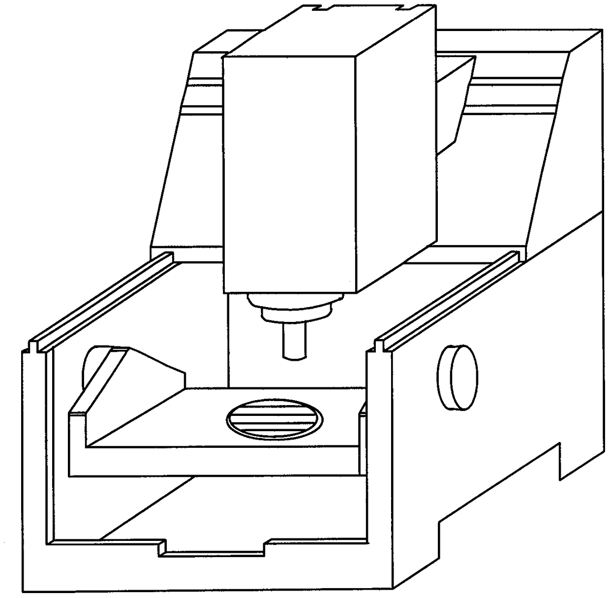
[0046] attached figure 1 Shown is a schematic structural diagram of a five-axis CNC machine tool, and the method of the present invention is described by taking the machine tool as an example.

[0047]In step 1, install the ballbar according to the structure of the machine tool and the position of the rotary axis, and calibrate the tool cup of the spindle and the tool cup of the base, including steps:

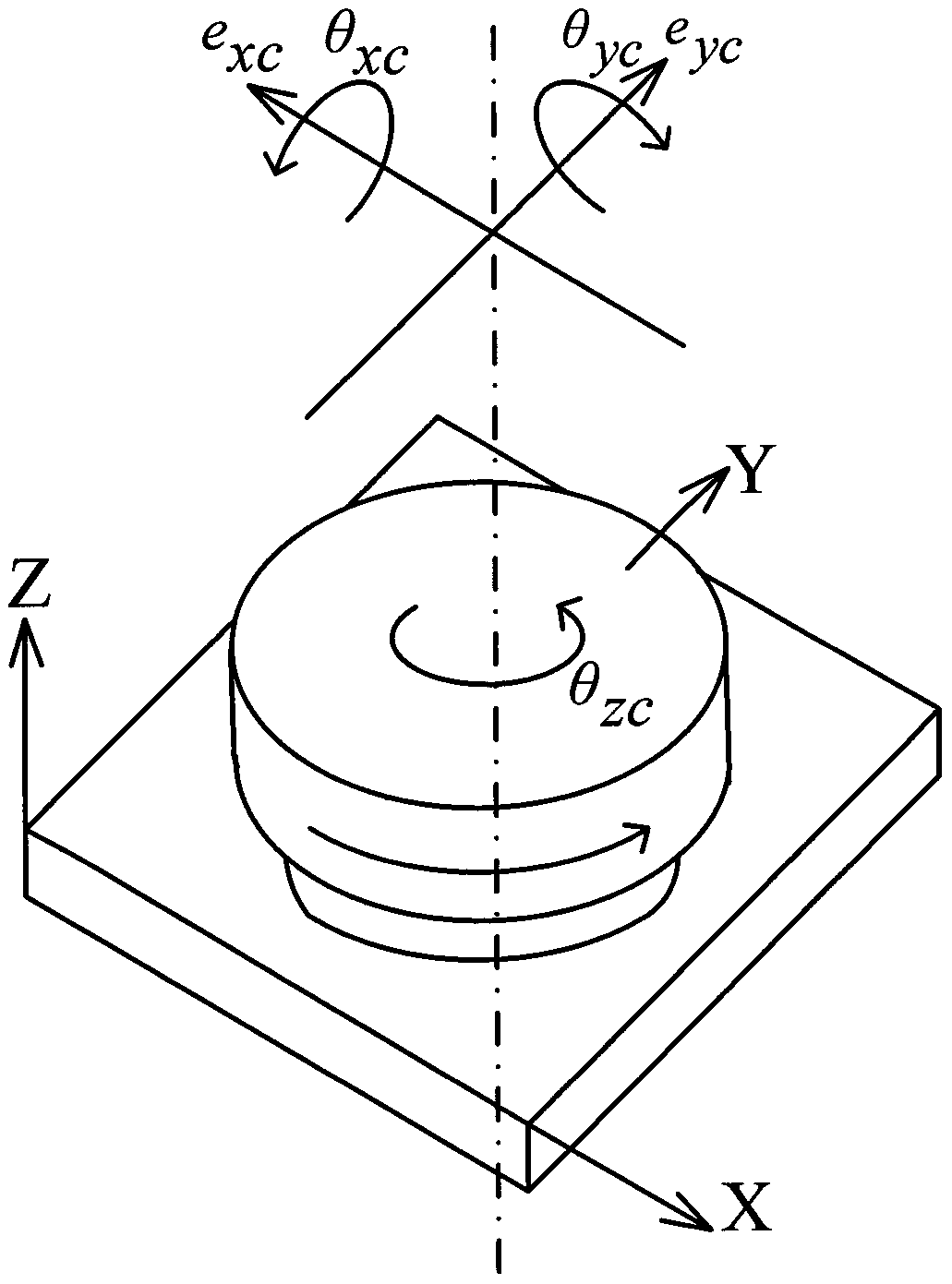
[0048] Step 1.1. Define the reference coordinate system. The origin of the reference coordinate system is located at the intersection of the A-axis axis and the C-axis axis. At the same time, the A-axis local coordinate system is established with the intersection of the A-axis axis and the A-axis turntable as the origin, and the C-axis axis The point of intersection with the C-axis turntable is the origin to establish the C-axis local coordina...


PUM


Abstract

The invention discloses a machine tool rotating shaft geometric error identification method based on ballbar measurement. The machine tool rotating shaft geometric error identification method based onballbar measurement comprises the following steps of according to the positions of a machine tool structure and a rotating shaft, installing a ballbar, and calibrating a main shaft tool cup and a base tool cup; utilizing a corresponding machine tool code for controlling only one rotating shaft of the machine tool to rotate; utilizing the ballbar for preliminarily identifying geometric errors, irrelevant to the position, of the rotating shaft; and changing the installation position of a ballbar base, utilizing the ballbar for accurately identifying the geometric errors, irrelevant to the position, of the rotating shaft, and obtaining eight geometric errors, irrelevant to the position, of the rotating shaft of the machine tool. The method provided by the invention can be used for quickly and effectively identifying the geometric errors of the rotating shaft of the machine tool, and is high in identification accuracy and good in practicability.

Description

technical field [0001] The invention relates to the technical field of error measurement of multi-axis numerically controlled machine tools, in particular to a method for identifying geometric errors of machine tool rotary axes based on ballbar measurement. technical background [0002] Five-axis CNC machining can effectively improve the surface finish of machined parts and has a better material removal rate, so it is widely used in modern manufacturing. Most of the advantages of five-axis machines are that they are more flexible than three-axis machines when performing CNC machining because they have two rotary axes that can orient the workpiece relative to the tool. However, two rotary axes also introduce more sources of error into the machine tool. The existing methods for measuring the error of three-axis machine tools can no longer meet the needs of error measurement for five-axis machine tools. Therefore, in order to maintain the accuracy of the machine tool, it is ne...

Claims


Application Information

Patent Timeline
Patent Type & Authority Applications(China)
IPC IPC(8): B23Q17/22
Inventor 蒋晓耕姚思涵
Owner TIANJIN POLYTECHNIC UNIV
Why Eureka
Try Eureka