Installation method of reinforcing steel bar insulated sleeve

A technology of insulating sleeve and steel bar, which is applied in the field of steel insulating sleeve piercing, can solve the problems of high cost, complex structure of the retrieving device, and non-operation, etc., and achieve a favorable effect for heating

Active Publication Date: 2018-12-11
河南省鼎鼎实业有限公司
View PDF7 Cites 5 Cited by
  • Summary
  • Abstract
  • Description
  • Claims
  • Application Information

AI Technical Summary

Problems solved by technology

[0008] Aiming at the defects of high manpower and material resources for manual threading of insulating sleeves, long-distance steel bar threading equipment is not suitable for short-distance steel bar threading, the structure of the retrieving device is complicated, the cost is high, and thermoplastic pipes are not processed, the invention provides A method for piercing reinforced insulating casings, the purpose of which is to realize the piercing of insulating plastic casings, heat shrinkage, and replace manual piercing, which can improve the efficiency of casing piercing, reduce the labor intensity of workers, and eliminate ballastless casings. The eddy current generated by the track when the train passes through improves the operation stability of the passenger dedicated line system

Method used


Image

  • Installation method of reinforcing steel bar insulated sleeve
  • Installation method of reinforcing steel bar insulated sleeve
  • Installation method of reinforcing steel bar insulated sleeve

Examples


Embodiment Construction

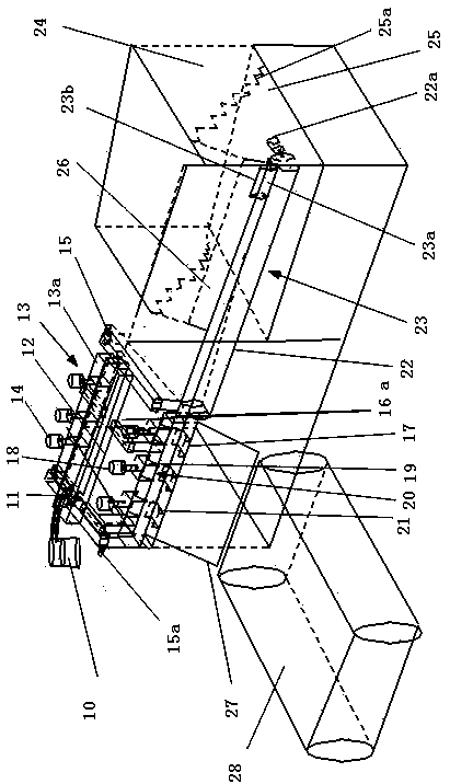
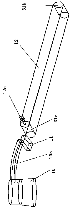
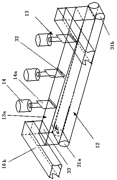
[0045] The specific technical solutions of the present invention will be described in detail below in conjunction with the accompanying drawings. In the following description, the left-right direction facing the device is defined as the horizontal direction, the front-rear direction facing the device is defined as the depth direction, and the vertical direction is defined as the vertical direction. It should be noted that, in figure 1 with image 3 as well as Figure 4 The positions of the middle vertical connecting rod 33 and the front depth connecting rod or the rear depth connecting rod are inconsistent, but are consistent in actual use. In actual use, the connection position can be determined according to the actual situation.

[0046] A method for piercing reinforced insulating sleeves, including a vibrating hopper, the method for piercing reinforced insulating sleeves is implemented in a device for piercing reinforced insulating sleeves, the device for piercing reinfo...


PUM


Abstract

The invention discloses an installation method of a reinforcing steel bar insulated sleeve, and belongs to the field of HSR (High-Speed Rail). The reinforcing steel bar insulated sleeve comprises a vibrating hopper. The installation method of the reinforcing steel bar insulated sleeve is implemented in a reinforcing steel bar insulated sleeve installation device, wherein the reinforcing steel barinsulated sleeve installation device comprises a carrying and separating device of an insulated sleeve, a carrying and transmitting device of reinforcing steel bars, a sleeve heating and shrinking device and a controller, wherein after the insulated sleeve is separated on the carrying and separating device, the insulated sleeve is transmitted into a groove for fixing after separating, the reinforcing steel bars are installed in the insulated sleeve by utilizing the carrying and transmitting device of the reinforcing steel bars; heating and shrinking can be realized by the sleeve heating and shrinking device. According to the installation method disclosed by the invention, manual installation is replaced, the installation efficiency of a sleeve can be increased, the labor intensity of a worker is reduced, vortex generated when a train passes through a ballastless track can be removed, and the running stability of a passenger transport line can be increased.

Description

technical field [0001] The invention relates to a method for piercing a casing, in particular to a method for piercing a reinforced insulating casing, which belongs to the field of high-speed rail. Background technique [0002] Ballastless track refers to the track structure that uses concrete, asphalt mixture and other integral foundations to replace the loose-grained gravel track bed, also known as ballastless track, which is an advanced track technology in the world today. [0003] The ballastless track is composed of steel rails, fasteners, and unit plates, which play the role of shock absorption and decompression. The sleepers of the ballastless track are poured concrete, and the roadbed does not use gravel, and the steel rails and sleepers are directly laid on the concrete road. Ballastless track is an advanced track technology in the world today, which can reduce maintenance, reduce dust, beautify the environment, and is more comfortable, and the train speed can reac...

Claims


Application Information

Patent Timeline
Patent Type & Authority Applications(China)
IPC IPC(8): B29C63/42B29C31/08B29C35/02
CPCB29C31/08B29C35/02B29C63/42
Inventor 王焕景庄振伟
Owner 河南省鼎鼎实业有限公司
Why Eureka
Try Eureka