Compression mold with overflow holes and fitting and preparation scheme thereof

An overflow hole and mold technology, applied in the field of molding molds, can solve the problems of decreased tensile strength, affected surface smoothness, structural changes, etc., and achieve the effects of increased tensile strength, uniform thickness, and no change in structure.

Pending Publication Date: 2018-12-11
HANGZHOU YOUKAI BOAT CO LTD
View PDF1 Cites 2 Cited by
  • Summary
  • Abstract
  • Description
  • Claims
  • Application Information

AI Technical Summary

Problems solved by technology

[0002] In order to increase the fiber density ratio of the existing fiber composite materials, during the manufacturing process, the fiber cloth is coated or pre-soaked with a liquid substrate and then laminated, and part of the liquid is pressed out. During the molding process, the liquid is along the upper mold. , The core of the lower mold flows and overflows to the outer periphery, which is easy to move the fibers, such as carbon fiber, glass fiber, ceramic fiber, basalt fiber and other brittle fibers. After the fiber moves, it bends, and the bending reduces the tensile strength, and the laminated object surface appears Partial protrusions, uneven thickness, and structural changes affect the smoothness of the surface, especially for fiber non-woven fabrics, which are more serious

Method used


Image

  • Compression mold with overflow holes and fitting and preparation scheme thereof
  • Compression mold with overflow holes and fitting and preparation scheme thereof
  • Compression mold with overflow holes and fitting and preparation scheme thereof

Examples


Embodiment 1

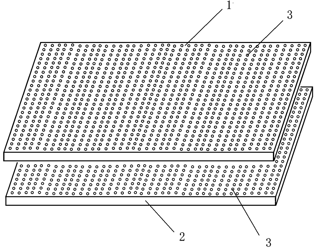
[0020] Molding molds and accessories with overflow holes and their preparation plan, including the upper mold 1 and the lower mold 2 of the mold, from the surface of the laminated object in the mold to the outside of the mold, adopt the method of mechanical drilling or laser perforation, and set the distribution evenly Several small overflow holes 3 are suitable for flat, oval and shell molds. For example, in some irregular parts of the shell mold, the overflow holes 3 provided may be uneven. For the parts mentioned above, first lay a fixed metal wire interwoven fabric along the inner wall of the mould. The metal wire interwoven fabric can be fixed on the outer periphery of the upper mold 1 and the lower mold 2, and a small number of small points on the inner wall, and then lay a fixed fiber interwoven fabric. The fixing method can be adopted Adhesively fix it on the outer periphery of the mold edge and a small number of small points on the inner wall, and then lay and fix the...

Embodiment 2

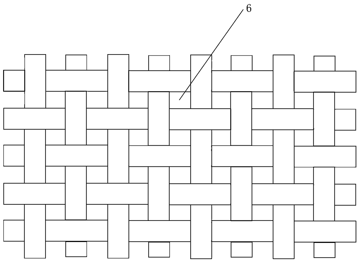
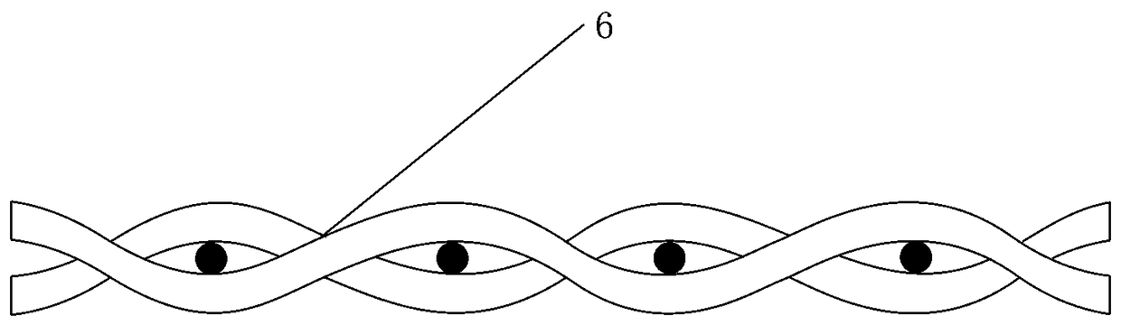
[0022] The upper mold 1 and the lower mold 2 of the molding die can be used without overflow holes 3, and according to the requirements of the pressed object and the number of layers, the thickness is different, and the upper mold 1 or the lower mold 2 without overflow holes can also be used; Only install accessories on the inner wall of the mold. The inner wall of the mold is firstly laid with a single layer of fixed metal wire or a double layer of metal wire in the warp and weft direction, then laid with a fixed metal wire interwoven fabric, then laid with a fixed fiber interwoven fabric, and then laid a fixed fiber felt, and then placed in During the pressing process after the pressed object, the liquid first overflows from the gap 6 of the fiber felt surface on the pressing surface, and then flows to the gap 6 of the fiber interwoven cloth, most of which flow to the metal wire interwoven fabric, and a small part flows to the mold along the interlayer The edge, then flows to...


PUM


Abstract

The invention discloses a compression mold with overflow holes and a fitting and a preparation scheme thereof. The compression mold comprises an upper mold, a lower mold and a fitting part, wherein aplurality of uniformly distributed overflow holes are formed in the inner walls of the upper mold and the lower mold to the outside of the mold, and a fixed fitting is laid on the inner wall of the mold; the fitting comprises a metal wire layer and a mixed fabric layer. The compression mold is used for compressing a fiber composite material, so that the fiber density ratio is improved; a laminateof a fiber cloth applied or pre-impregnated with a liquid base material is compressed, so that the excess liquid is reduced in the laminate, and thus the compressed object liquid uniformly overflows from the compression surface, and the fiber hardly moves during the compressing process, thereby solving the problems of tensile strength drop, fiber damage, uneven thickness, and structural change caused by the movement of fiber in the prior art.

Description

technical field [0001] The invention relates to molding processing equipment, in particular to a molding die. Background technique [0002] In order to increase the fiber density ratio of existing fiber composite materials, during the manufacturing process, the fiber cloth is coated or pre-impregnated with a liquid substrate and then laminated, and part of the liquid is pressed out. During the molding process, the liquid is along the upper mold. , The core of the lower mold flows and overflows toward the outer periphery, which is easy to move the fibers, such as carbon fiber, glass fiber, ceramic fiber, basalt fiber and other brittle fibers. After the fiber moves, it bends, and the bending reduces the tensile strength, and the laminated surface appears Partial protrusions, uneven thickness, and structural changes affect the smoothness of the surface, especially for fiber non-woven fabrics. Contents of the invention [0003] In order to overcome the technical problem of fi...

Claims


Application Information

Patent Timeline
Patent Type & Authority Applications(China)
IPC IPC(8): B29C70/34B29C33/00
CPCB29C33/00B29C70/345
Inventor 骆恩浩王宗毅
Owner HANGZHOU YOUKAI BOAT CO LTD
Why Eureka
Try Eureka