Electric vehicle

A technology for electric vehicles and vehicles, applied in electric vehicles, vehicle energy storage, electric vehicle charging technology, etc., to achieve the effect of easy replacement operations and easy opening and closing operations

Active Publication Date: 2018-12-11
HONDA MOTOR CO LTD
View PDF12 Cites 6 Cited by
  • Summary
  • Abstract
  • Description
  • Claims
  • Application Information

AI Technical Summary

Problems solved by technology

Therefore, in the prior art, there is room for improvement in terms of absorbing the phase difference between the...

Method used


Image

  • Electric vehicle
  • Electric vehicle
  • Electric vehicle

Examples


Embodiment Construction

[0032] Hereinafter, embodiments of the present invention will be described with reference to the drawings.

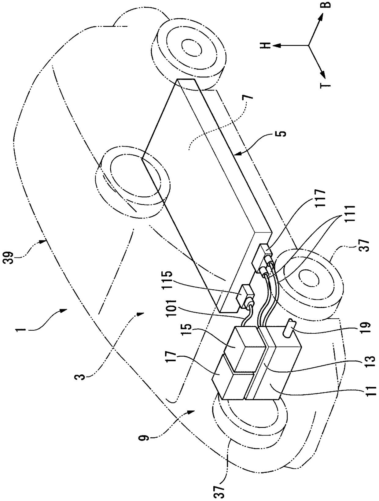
[0033] figure 1 It is a perspective view which shows the schematic structure of the electric vehicle 1 which concerns on one Embodiment of this invention.

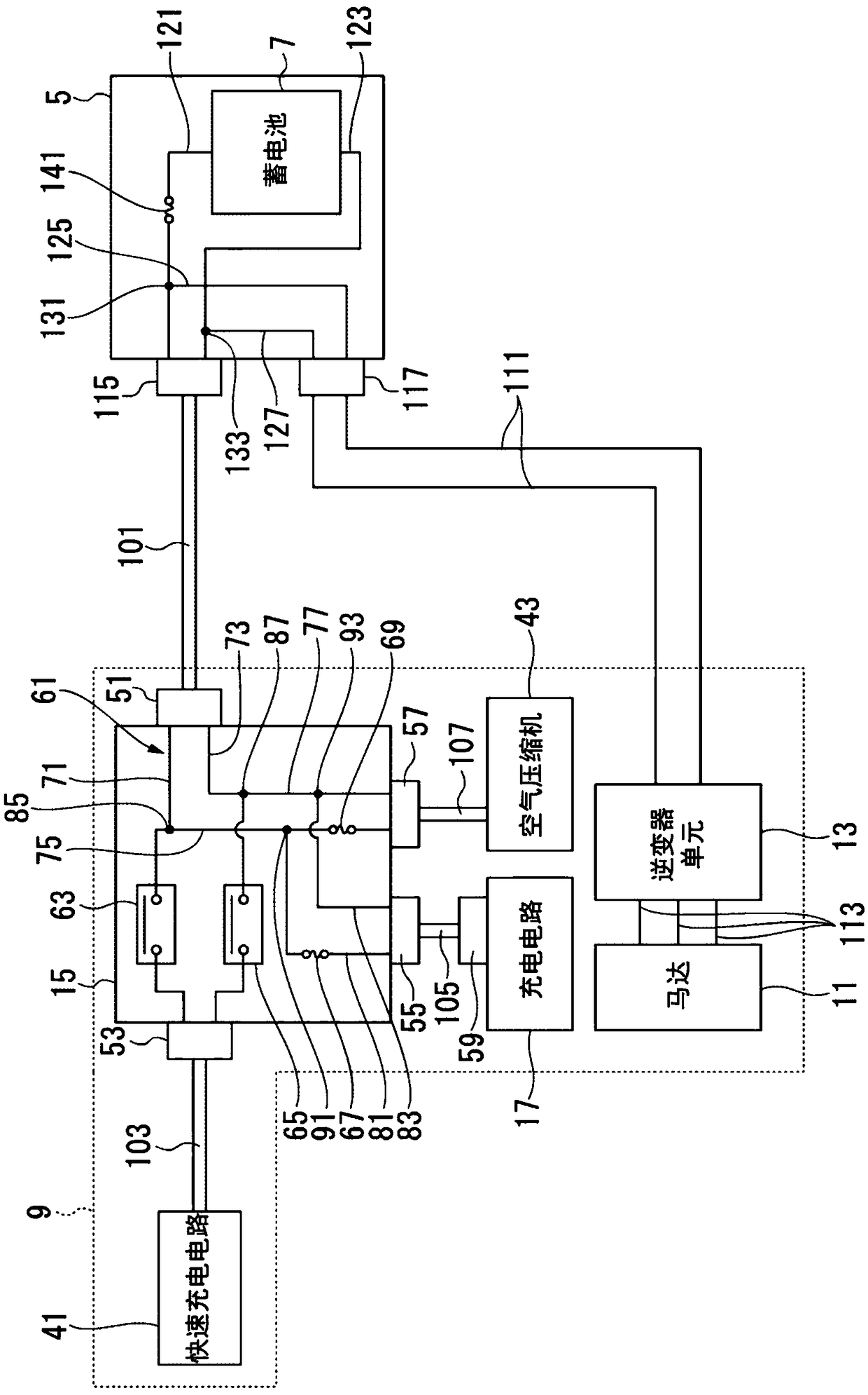
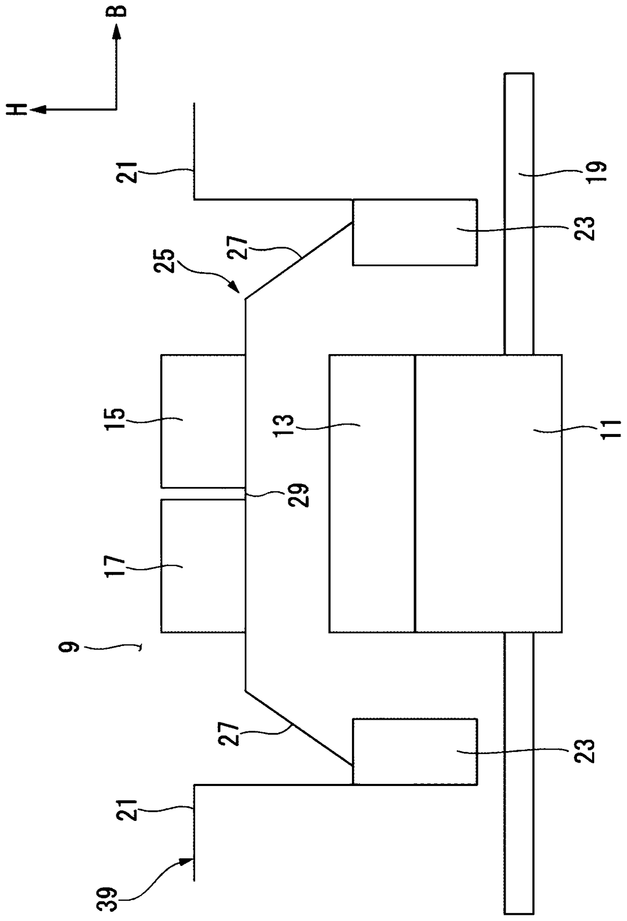
[0034] figure 2 It is a block diagram showing the structure in the motor room of the electric vehicle of the embodiment and the structure in the battery case.

[0035] The directions of front, rear, left, right, and up in the following description are the same as those of the electric vehicle 1 , unless otherwise specified. In addition, arrow T in each figure represents the front of the vehicle, arrow B represents the left side of the vehicle, and arrow H represents the upper side of the vehicle.

[0036] like figure 1 As shown, in the vehicle body 39 of the electric vehicle 1 , the battery case 5 is mounted on the underfloor portion of the vehicle compartment 3 . like figure 2 As shown, a battery 7 (power s...


PUM


Abstract

The present invention provides an electric vehicle that can easily swing and absorb a phase difference of vibrations of different components of a vibration system. The electric vehicle includes: a motor (11) that is arranged on one of the front and rear sides of the vehicle (1); an electric source (7) that is arranged closer to a vehicle room (3) than the motor (11); an inverter unit (13) that isfixed on the motor and includes an inverter which is configured to control and drive the motor (11) by electric power that is supplied from the electric source (7); a charge circuit (17) for chargingthe electric source; and a first unit (15) that is fixed to one side of the vehicle body (39), wherein the inverter unit (13) is connected to the electric source (7) by a cable (111), and the first unit (15) is connected to the electric source (7) by a cable (101) that is independent of the cable (111) which connects together the inverter unit (13) and the electric source (7).

Description

technical field [0001] The present invention relates to electric vehicles. Background technique [0002] Conventionally, among electric vehicles, for example, there is an electric vehicle shown in Japanese Patent Application Laid-Open No. 2013-115957. The electric vehicle of Japanese Patent Application Laid-Open No. 2013-115957 includes a motor, a battery as a power source, an inverter unit, a charger, an electric compressor, and a branch unit. [0003] The motor is arranged in a motor room provided on the front side of the vehicle. The battery is arranged at a position closer to the vehicle compartment than the motor, and can be charged. The inverter unit is fixed to the motor, and drives and controls the motor with electric power supplied from the battery. The charger is used to charge the battery. The electric compressor is arranged on the front side of the vehicle, and is driven by electric power supplied from the battery. The branch unit is arranged in the inverter...

Claims


Application Information

Patent Timeline
IPC IPC(8): B60L11/18H02J7/00
CPCH02J7/0045H02J7/0068B60L53/22B60L50/51B60K1/04H02J7/02H02J7/14B60L2270/145B60L53/11B60L50/70B60L15/007B60K1/00H02P27/06H02J2310/48Y02T10/64Y02T90/40Y02T10/70Y02T10/7072Y02T90/14
Inventor 播田实慎
Owner HONDA MOTOR CO LTD
Why Eureka
Try Eureka