A road garbage cleaning and collecting device

A collection device and garbage technology, applied in road cleaning, cleaning methods, construction, etc., can solve problems such as threats to personal safety, low efficiency of road cleaning and garbage cleaning, and achieve the effect of improving transportation efficiency

Active Publication Date: 2020-04-03
轩昂环保科技股份有限公司
View PDF6 Cites 0 Cited by
  • Summary
  • Abstract
  • Description
  • Claims
  • Application Information

AI Technical Summary

Problems solved by technology

[0004] In order to solve the defects in the prior art that the efficiency of common road cleaning and garbage cleaning is low, and the personal safety of sanitation workers is threatened during the cleaning and cleaning process on the road, the invention provides a road garbage cleaning and collection device

Method used


Image

  • A road garbage cleaning and collecting device
  • A road garbage cleaning and collecting device
  • A road garbage cleaning and collecting device

Examples


Embodiment 1

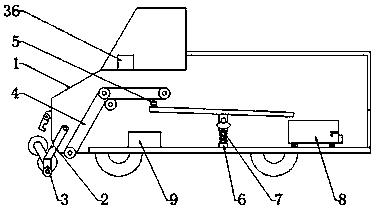
[0033] Embodiment 1: as Figure 1-9 Shown, a kind of road garbage cleaning and collecting device of the present invention comprises car body 1, also includes:

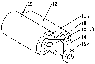
[0034] The movable frame 2 placed at the bottom of the front of the vehicle body 1, the top of the movable frame 2 is hinged with the vehicle body 1, and the bottom of the movable frame 2 is provided with a cleaning mechanism 3 for cleaning the ground and collecting garbage. The cleaning mechanism 3 includes a first electric roller 10 and the second motorized roller 11, and the outside of the first motorized roller 10 and the second motorized roller 11 are sleeved with a brush cover 12, and the first motorized roller 10 and the second motorized roller 11 rotate in opposite directions , the first motorized roller 10 and the second motorized roller 11 can be supported by the movable frame 2, and direct contact and friction between the first motorized roller 10 and the ground can be avoided, and the first motorized roller...

Embodiment 2

[0041] Example 2, such as figure 1 and 3 As shown, the surface of the front of the car body 1 is provided with a hook for accommodating the movable frame 2, and the middle part of the movable frame 2 is provided with a hook groove matching the hook, and the first electric roller 10 and the second electric roller 11 Both ends are provided with connecting plates 13, and the outsides of the two connecting plates 13 are provided with supporting plates 14, and the bottoms of the two supporting plates 14 are provided with movable wheels 15, and the movable frame 2 is rotationally connected with the connecting plate 13 top, and the movable frame One end of 2 makes the movable wheel 15 contact the ground through the connecting plate 13 and the supporting plate 14. The hook and the hook groove can facilitate the staff to store the movable frame 2. The movable wheel 15 can make the distance between the first electric roller 10 and the ground It is stable and avoids friction of the firs...

Embodiment 3

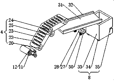
[0042] Example 3, such as Figure 4 As shown, the middle parts of the two ends of the second electric roller 11 are provided with rotating rods 16, and the outsides of the two rotating rods 16 are sleeved with movable blocks 17, and the two rotating rods 16 are rotationally connected with the inside of the movable block 17, and the movable One side of the block 17 is slidably connected with the slide bar 18, the slide bar 18 is positioned in the groove on one side of the connecting plate 13, and the top of the slide bar 18 is sleeved with a first spring 19, through the movable block 17, the slide bar 18 and the first The spring 19 not only improves the cleaning and collecting effect of the first motorized roller 10 and the second motorized roller 11, but also protects the second motorized roller 11 to prevent the first motorized roller 10 and the second motorized roller 11 from Damage occurs when a foreign object gets stuck in it.


PUM


Abstract

The invention discloses a road garbage cleaning and collecting device, which includes the vehicle body, and a movable frame arranged at the bottom of the front of the vehicle body; the top end of themovable frame is articulated with the vehicle body, A cleaning mechanism for cleaning the floor and collecting garbage is arranged at the bottom of the movable rack, the cleaning mechanism includes afirst electric roller and a second electric roller, and a brush sleeve is sleeved on the exterior of the first electric roller and the second electric roller, the first electric roller and the secondelectric roller are rotated in opposite directions, the invention can support a first electric roller and a second electric roller through a movable frame, the first electric roller can be well protected, the brush sleeve can be driven to rotate by a first electric roller and a second electric roller which are relatively rotated, When the brush sleeve on the first electric roller is in contact with the rubbish on the ground, the rubbish can be swept upward, and then the rubbish is led into the vehicle body by the brush sleeve on the second electric roller, so that the rubbish on the ground canbe not only swept but also collected.

Description

technical field [0001] The invention relates to a garbage cleaning device, in particular to a road garbage cleaning and collecting device. Background technique [0002] From the meaning of the word, the road is the infrastructure for various trackless vehicles and pedestrians; according to its use characteristics, it can be divided into highways, urban roads, country roads, factory and mine roads, forestry roads, examination roads, competition roads, automobile test roads, workshop passages and school roads etc. [0003] There are often rubbish and sundries on the common roads. Foreign matter on the road can easily affect the driving of vehicles. The common way to clean up road rubbish and foreign matter is for sanitation workers to go to the road to clean up foreign matter on the road. The cleaning efficiency is low, and The sanitation staff cannot guarantee the personal safety of the staff during the cleaning process, and the sanitation staff shuttling on the road will af...

Claims


Application Information

Patent Timeline
Patent Type & Authority Patents(China)
IPC IPC(8): E01H1/04
CPCE01H1/04E01H1/045E01H1/047
Inventor 朱亚凤
Owner 轩昂环保科技股份有限公司
Why Eureka
Try Eureka