
Hydraulic cylinder and control rod hydraulic drive system

A technology of hydraulic cylinders and control rods, which is applied in the field of nuclear reactors, can solve the problems of rubber sealing rings that are easy to age and deform, cannot support the inner sleeve, shorten the service life of the inner sleeve and outer sleeve, etc., so as to prolong the service life and prevent aging and deformation , the effect of prolonging the service life

Active Publication Date: 2021-11-26
TSINGHUA UNIV
View PDF12 Cites 0 Cited by
  • Summary
  • Abstract
  • Description
  • Claims
  • Application Information

AI Technical Summary

Problems solved by technology

However, the working environment of the nuclear reactor control rod hydraulic drive system is a high temperature, high pressure and irradiation environment. The rubber sealing ring is not only easily aged and deformed, but also unable to support the inner sleeve, resulting in direct contact and friction between the inner sleeve and the outer sleeve, thereby shortening the The service life of the inner and outer cylinders is improved

Method used


Image

  • Hydraulic cylinder and control rod hydraulic drive system
  • Hydraulic cylinder and control rod hydraulic drive system
  • Hydraulic cylinder and control rod hydraulic drive system

Examples


Embodiment Construction

[0039] In order to make the purpose, technical solutions and advantages of the invention clearer, the technical solutions in the invention will be clearly described below in conjunction with the accompanying drawings in the invention. Obviously, the described embodiments are part of the embodiments of the invention, not all of them. Example. Based on the embodiments of the invention, all other embodiments obtained by persons of ordinary skill in the art without making creative efforts belong to the protection scope of the invention.

[0040] In the description of the embodiments of the present invention, it should be noted that the terms "center", "longitudinal", "transverse", "upper", "lower", "front", "rear", "left", "right" , "vertical", "horizontal", "top", "bottom", "inner", "outer" and other indicated orientations or positional relationships are based on the orientations or positional relationships shown in the drawings, and are only for the convenience of describing thi...


PUM


Abstract

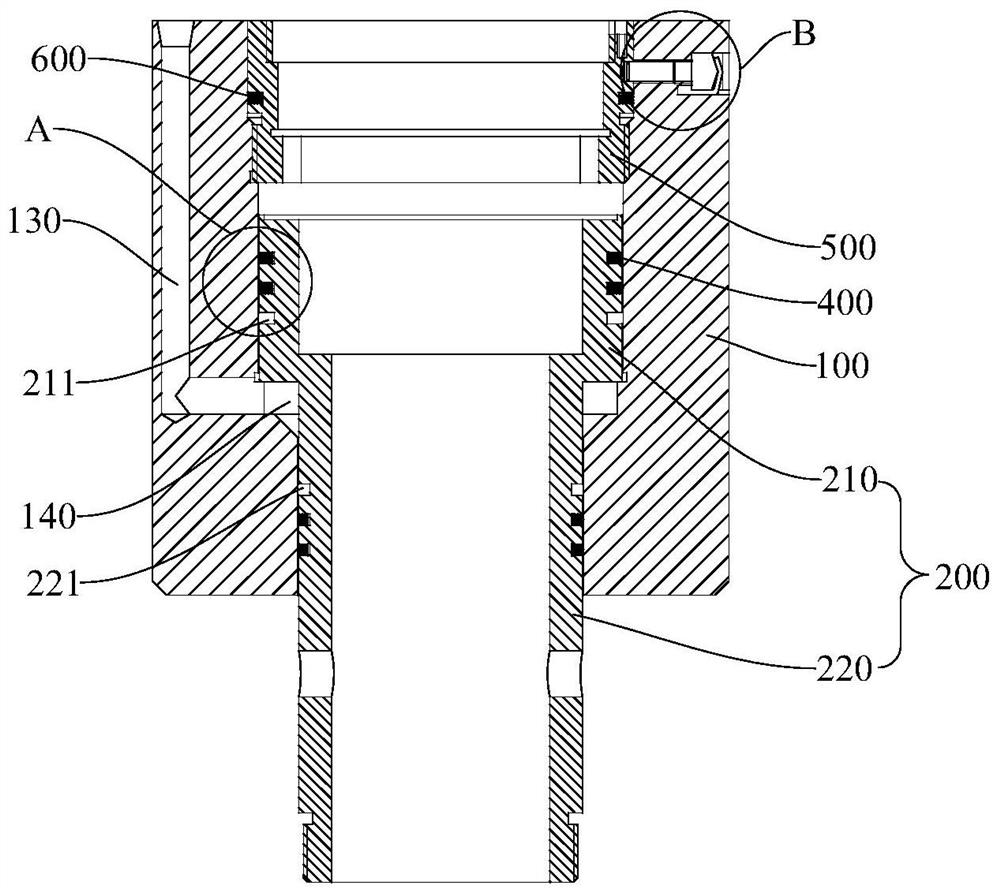
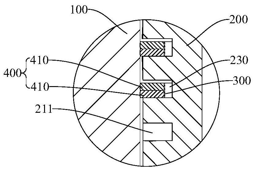
The invention relates to the field of nuclear reactors, and provides a hydraulic cylinder and a control rod hydraulic drive system. The hydraulic cylinder includes an outer casing and an inner casing. The inner chamber of the outer casing includes an upper chamber and a lower chamber communicating with the upper chamber. A stepped surface is formed between the upper chamber and the lower chamber, and a hydraulic ring groove is opened on the stepped surface. , the side wall of the outer casing is provided with a water inlet channel communicating with the hydraulic ring groove; the inner casing includes an upper casing located in the upper cavity and a lower casing located in the lower cavity, and the outer walls of the upper casing and the lower casing are provided with The first ring groove, the first ring groove is provided with an elastic support ring and a piston ring assembly sequentially along its radial direction from inside to outside, and the elastic support ring is used to drive the piston ring assembly part out of the first ring groove, so that the piston ring The assembly is in sliding and sealing engagement with the inner wall of the outer casing. The control rod hydraulic drive system includes a hydraulic cylinder. The invention utilizes the elastic support ring to realize the suspension support for the inner sleeve cylinder, avoids direct contact and friction between the inner sleeve cylinder and the outer sleeve cylinder, and prolongs the service life of the hydraulic cylinder.

Description

technical field [0001] The invention relates to the technical field of nuclear reactors, in particular to a hydraulic cylinder and control rod hydraulic drive system. Background technique [0002] At present, the hydraulic drive system of nuclear reactor control rods usually utilizes the cooperation of lifting hydraulic cylinders, transfer hydraulic cylinders and clamping hydraulic cylinders to realize the functions of step-up, step-down and rod drop of control rods. When the above functions are realized, the inner sleeve cylinder of the lifting hydraulic cylinder, the transmission hydraulic cylinder or the clamping hydraulic cylinder slides relative to the outer sleeve cylinder. In order to ensure the tightness, the outer wall of the inner sleeve is usually equipped with a rubber sealing ring. However, the working environment of the nuclear reactor control rod hydraulic drive system is a high temperature, high pressure and irradiation environment. The rubber sealing ring i...

Claims


Application Information

Patent Timeline
Patent Type & Authority Patents(China)
IPC IPC(8): F15B15/14F15B15/24F16J9/06F16J9/16F16J9/26F16J10/04G21C7/16
CPCF15B15/14F15B15/1428F15B15/1447F15B15/1452F15B15/149F15B15/24F16J9/064F16J9/069F16J9/16F16J9/26F16J10/04G21C7/16Y02E30/30
Inventor 薄涵亮王大中张作义赵陈儒秦本科王金海刘潜峰
Owner TSINGHUA UNIV
Learn More