Kitchen waste treatment system

A technology for processing system and kitchen waste, which is applied to indoor sanitary pipeline installations, water supply installations, buildings, etc. It can solve the problems of clogged sewers, perishable, easy to produce rotten smell, etc., and achieve the effect of preventing clogging

Inactive Publication Date: 2018-12-11
李玉娟
View PDF0 Cites 1 Cited by
  • Summary
  • Abstract
  • Description
  • Claims
  • Application Information

AI Technical Summary

Problems solved by technology

[0002] In people's daily life, there will be a large amount of food waste every day, which is the food leftovers discarded during food processing, food leftovers after eating, and untreated waste produced in the process of cleaning food and washing tableware. Sewage and food waste mainly include fruit peels, broken bones, vegetable roots and leaves, etc. In real life, people usually collect food waste in garbage bags, and throw them into garbage bins when the garbage bags are full, and then sanitation staff will The garbage in the fully loaded garbage bins is transported by garbage trucks to the garbage disposal station for centralized treatment. It takes a long time and long-distance transportation from garbage generation to treatment. Because various organic substances contained in kitchen garbage are extremely perishable, garbage Pollution is caused during the collection, stacking and transportation process, which not only easily attracts mosquitoes and flies to spread germs, but also easily produces spoilage smell, which affects the surrounding environment
[0003] Based on the above problems, it is best to deal with kitchen waste by technology. However, the existing household kitchen waste treatment system has a single function, and the garbage is not crushed thoroughly enough, which leads to the problem of blocking the sewer during the discharge process, which brings great harm to people's lives. It is very inconvenient, and because the existing household kitchen waste equipment is relatively large in size and expensive, individual households cannot afford it.

Method used


Image

  • Kitchen waste treatment system
  • Kitchen waste treatment system
  • Kitchen waste treatment system

Examples


Embodiment Construction

[0040] The present invention will be described in further detail below in conjunction with the accompanying drawings and embodiments, so that those skilled in the art can implement it with reference to the description.

[0041] It should be understood that terms such as "having", "comprising" and "including" as used herein do not entail the presence or addition of one or more other elements or combinations thereof.

[0042] It should be noted that the experimental methods described in the following embodiments, unless otherwise specified, are conventional methods, and the reagents and materials, unless otherwise specified, can be obtained from commercial sources.

[0043] In the description of the present invention, the terms "transverse", "longitudinal", "upper", "lower", "front", "rear", "left", "right", "vertical", "horizontal", " The orientations or positional relationships indicated by "top", "bottom", "inner", "outer", etc. are based on the orientations or positional rel...


PUM


Abstract

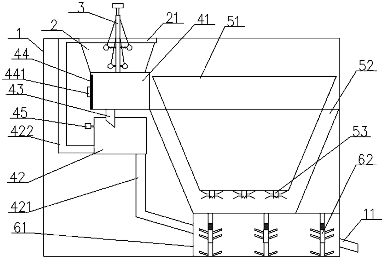
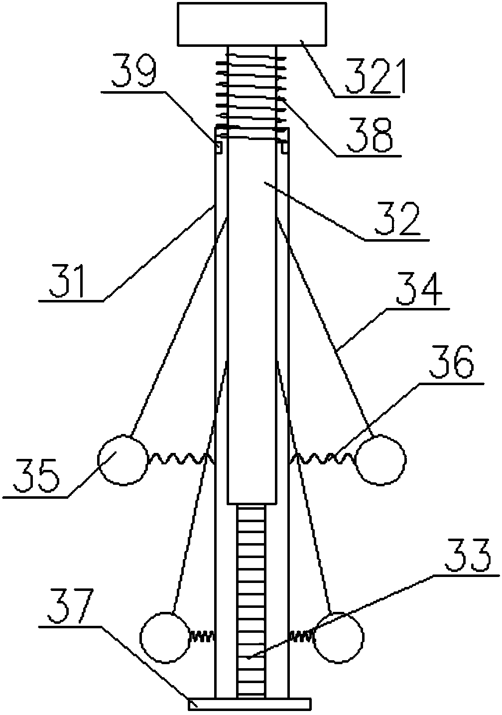
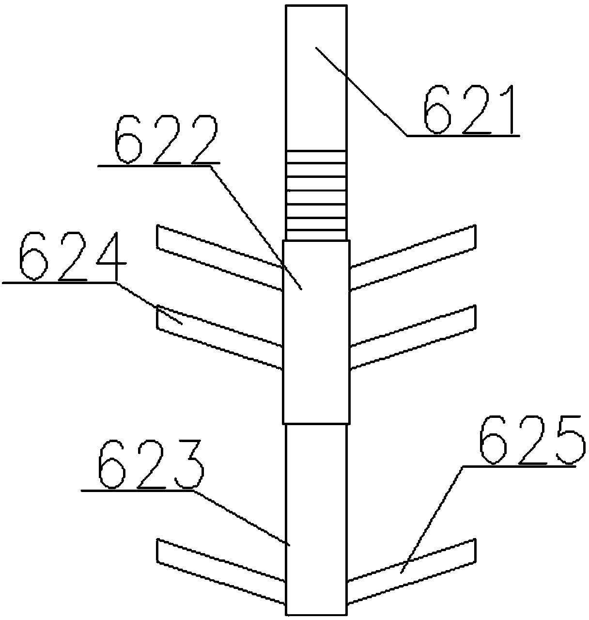
The invention discloses a kitchen waste treatment system. The kitchen waste treatment system comprises a box body, a material charge hopper, a material charge mechanism, a suction filtration mechanism, a crushing mechanism and a material discharge mechanism, wherein the material charge mechanism comprises a first cylinder body, a second cylinder body, a first screw rod and a plurality of groups ofmaterial discharge assemblies; the suction filtration mechanism comprises a material storage box, a liquid storage box and a first pipe body; the crushing mechanism comprises a first rotary body anda second rotary body; the material discharge mechanism comprises a material discharge box and a plurality of stirring assemblies. The kitchen waste treatment system has the advantages that the kitchenwaste can be timely and thoroughly crushed, and be smoothly discharged via a sewer, and the blockage accident of the sewer is prohibited; the structure is simple, the manufacturing cost is lower, theconsumption level of more users can be met, and the economy and practicality are higher.

Description

technical field [0001] The invention relates to the technical field of garbage disposal. More specifically, the present invention relates to a food waste treatment system. Background technique [0002] In people's daily life, there will be a large amount of food waste every day, which is the food leftovers discarded during food processing, food leftovers after eating, and untreated waste produced in the process of cleaning food and washing tableware. Sewage and food waste mainly include fruit peels, broken bones, vegetable roots and leaves, etc. In real life, people usually collect food waste in garbage bags, and throw them into garbage bins when the garbage bags are full, and then sanitation staff will The garbage in the fully loaded garbage bins is transported by garbage trucks to the garbage disposal station for centralized treatment. It takes a long time and long-distance transportation from garbage generation to treatment. Because various organic substances contained i...

Claims


Application Information

Patent Timeline
Patent Type & Authority Applications(China)
IPC IPC(8): E03C1/266
CPCE03C1/2665
Inventor 李玉娟
Owner 李玉娟
Why Eureka
Try Eureka