Oil pipe perforator and method for preventing throttling mouth from choking

A technology for a hole punch and an oil pipe, applied in the field of hole punch, can solve the problems of high manufacturing cost, complex structure, inconvenient use, etc., and achieve the effects of low manufacturing cost, smooth forward and reverse movement, and convenient operation.

Pending Publication Date: 2018-12-11
西安荣达石油工程有限公司
View PDF0 Cites 2 Cited by
  • Summary
  • Abstract
  • Description
  • Claims
  • Application Information

AI Technical Summary

Problems solved by technology

[0004] The invention provides a new type of oil pipe puncher, which solves the technical problems of c

Method used


Image

  • Oil pipe perforator and method for preventing throttling mouth from choking
  • Oil pipe perforator and method for preventing throttling mouth from choking
  • Oil pipe perforator and method for preventing throttling mouth from choking

Examples


Embodiment 1

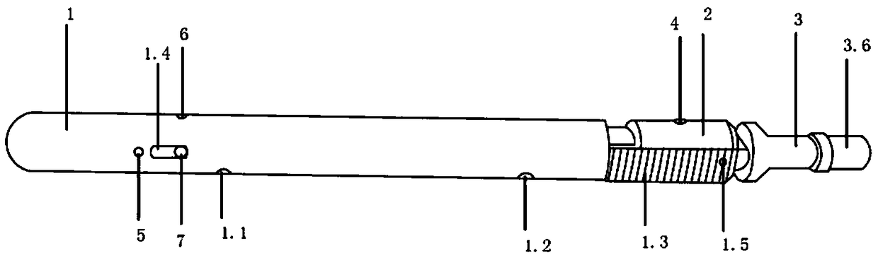
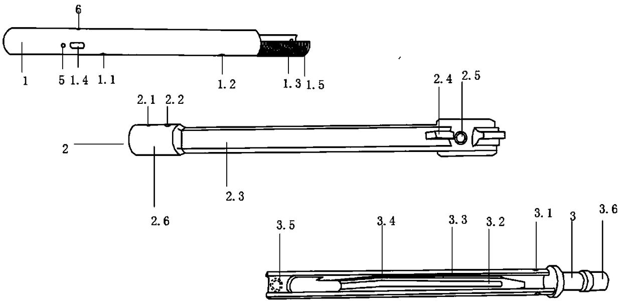
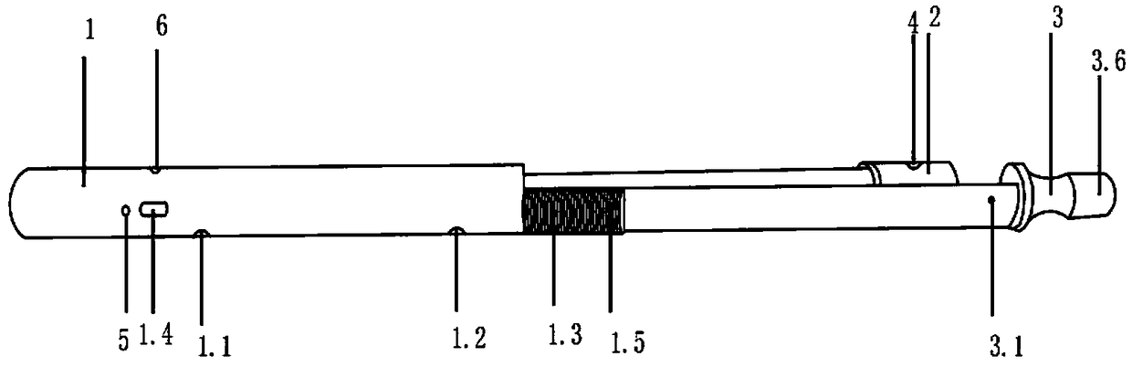
[0021] Example 1, such as Figure 1-Figure 5As shown, the oil pipe puncher includes a cylinder body 1, a body 2, a bracket 3, a punch 4 and a positioner 10; the outer end of the cylinder body 1 is provided with a semicircular slip 1.3, and the side of the cylinder body 1 The second positioning hole 1.2, the second shear pin hole 5 of the cylinder and the sliding hole 1.4 of the positioning pin are set on the wall; the connecting terminal 3.6 is set at the outer end of the support 3, and the support 3 body is a semicircular groove shape. 3 There are slideway 3.2, fixed slideway 3.3 and tapered slope 3.4 in the body groove, that is, the structure is inclined upward and then downward after reaching the highest point; the slideway 3.2 is set in the middle position to accommodate the sliding boss 2.4 Wherein it slides; the tapered slope 3.4 is arranged on both sides of the slideway 3.2; the fixed chute 3.3 is arranged on both sides of the slideway 3.2, and the both sides of the pun...

Embodiment 2

[0022] Example 2, such as Figure 4 As shown, the punch includes a punch head 4.1 and a punch seat 4.2, which are fixedly connected, preferably integrally cast or forged; the two sides of the punch seat 4.2 are symmetrically provided with a first inclined table surface 4.2.1 and a second inclined table surface 4.2 .2; the inclination direction of the first inclined table surface 4.2.1 and the second inclined table surface 4.2.2 are the same, and the upper and lower positions are opposite. The fixed chute 3.3 is also conical in parallel with the conical inclined surface 3.4, and the lower surface of the punch seat 4.2 is in contact with the conical inclined surface 3.4. Therefore, in the process of pulling the bracket 3 outward, because of the existence of the first inclined platform 4.2.1, the punch 4 is easier to slide relative to the tapered inclined surface 3.4, and will not be stuck; and after the drilling is completed, take out the oil pipe For the hole puncher, when it ...

Embodiment 3

[0023] Example 3, such as Figure 1-Figure 3 As shown, on the basis of the above-mentioned technical solution, the first positioning hole 1.1 is also arranged on the same side of the second positioning hole 1.2 and the positioning pin sliding hole 1.4 on the cylinder 1; the positioning pin 7 passes through the positioning pin hole 2.2 and the positioning The pin sliding hole 1.4 is provided, and can slide up and down along the positioning pin sliding hole 1.4. A fastening screw hole 6 is arranged vertically on the cylinder body 1 relative to the sliding hole 1.4 of the positioning pin. The middle part of the positioning pin 7 is an inner hexagonal structure. The inner hexagonal structure position in the middle is used to fix the positioning pin 7 to prevent the positioning pin 7 from running out or rotating.


PUM


Abstract

The invention belongs to the technical field of perforators, in particular to an oil pipe perforator and a method for preventing a throttling mouth from choking. The oil pipe perforator comprises a cylindrical shell (1), a body (2), a support (3), a punch (4) and a positioner (10). Improvements are made to the overall structure in order to realize the oil pipe perforator. When the support (3) is drawn outwards, the punch (4) outwardly rushes out and hits through an oil pipe wall. When the oil pipe wall is pierced, the punch (4) instantly contracts back. The positioner (10) is used for fixing the support (3) and the punch (4) such that the oil pipe perforator is not stuck from the oil pipe wall. Therefore, re-utilization is achieved. The invention also brings forward the method for preventing the throttling mouth from choking. Simple operation is achieved. The method has a notable effect on an oil-gas well which is equipped with the choked throttling mouth of a throttler and cannot be salvaged. Cost is low. High safety is achieved.

Description

technical field [0001] The invention belongs to the technical field of punching devices, and in particular relates to a novel oil pipe punching device and a method for solving the blocking problem of throttle nozzles of oil and gas wells by using the oil pipe punching device. Background technique [0002] In oil and natural gas development operations, the tubing hole puncher in the prior art often needs to drill holes on the tubing wall in order to ensure that there is a circulation channel between the tubing and the annular space during the downhole operation of the oil and gas well. The perforation gun is used to perforate the oil pipe wall. During the construction of the perforating gun, the perforating gun is lowered to the target layer to be perforated through the cable or coiled tubing, and the detonator is detonated through the cable or through the coiled tubing. Pressurized detonation of the pressure detonator connected with the coiled tubing to detonate the detonati...

Claims


Application Information

Patent Timeline
IPC IPC(8): E21B43/11E21B29/00E21B31/00
CPCE21B29/00E21B31/00E21B43/11
Inventor 董成利
Owner 西安荣达石油工程有限公司
Why Eureka
Try Eureka