
Energy-saving pressure-combining well head fracturing device

A wellhead device and fracturing technology, applied in wellbore/well components, production fluids, earthwork drilling, etc., can solve the problems of reducing safety risks, shortening construction period, economic losses, etc., to reduce safety risks and shorten construction period. , cost saving effect

Pending Publication Date: 2018-12-11
YANCHENG SUNDA PETROCHEMICAL MASCH CO LTD
View PDF6 Cites 7 Cited by
  • Summary
  • Abstract
  • Description
  • Claims
  • Application Information

AI Technical Summary

Problems solved by technology

[0002] During the downhole operation of the oil field, the hot fracturing controller (also known as blowout preventer) is mainly used for hot fracturing construction, directly connected to the KY65 / 25 oil production wellhead cross, and cooperates with the fracturing tubing hanger to realize hanging fracturing. The function of cracking the pipe string, preventing the rotation and lifting of the pipe string, and at the same time realizing the well control function with the high-pressure hydraulic control assembly can achieve the purpose of shortening the construction period and reducing safety risks. The original pressure equipment was removed before the fracturing operation. Reinstalling after fracturing is time-consuming and laborious, and there are many safety hazards when operating above, and the tubing suspension joint cannot effectively prevent the upward movement of the sucker rod, and the bearing capacity is also poor. It is lifted by the well fluid and hits the blowout preventer, causing damage to the blowout preventer and causing major economic losses

Method used


Image

  • Energy-saving pressure-combining well head fracturing device
  • Energy-saving pressure-combining well head fracturing device
  • Energy-saving pressure-combining well head fracturing device

Examples


Embodiment Construction

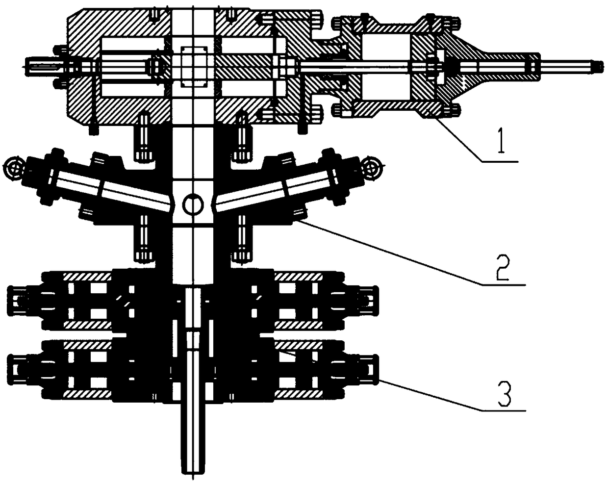
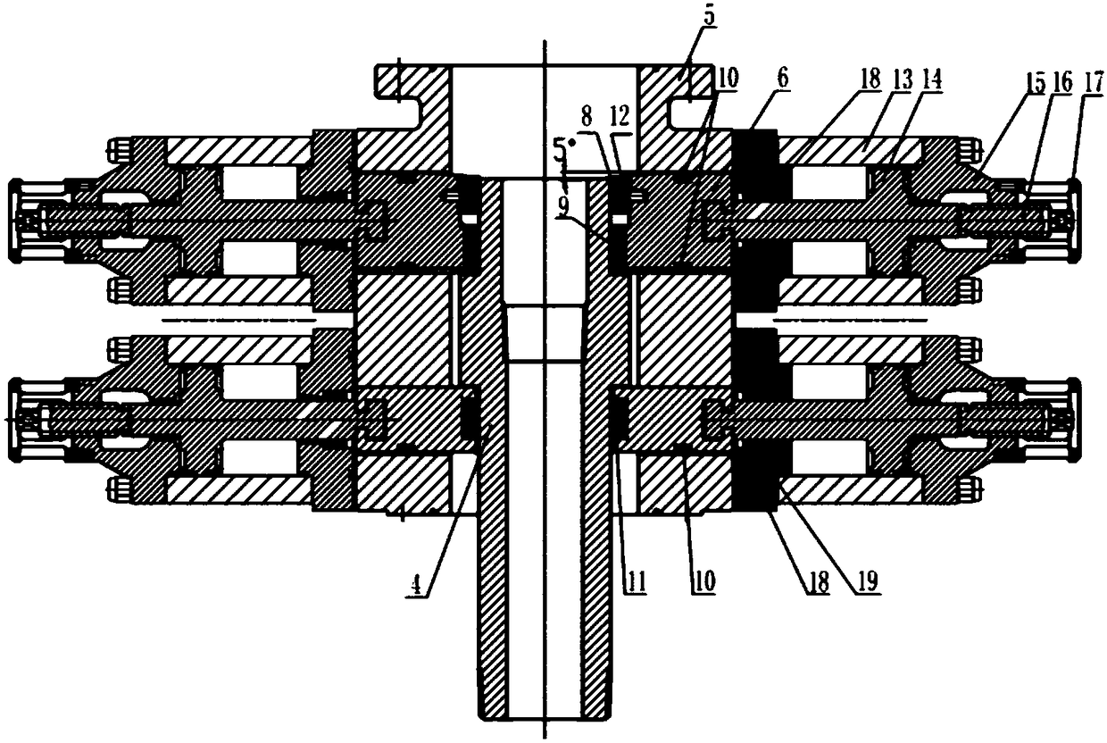
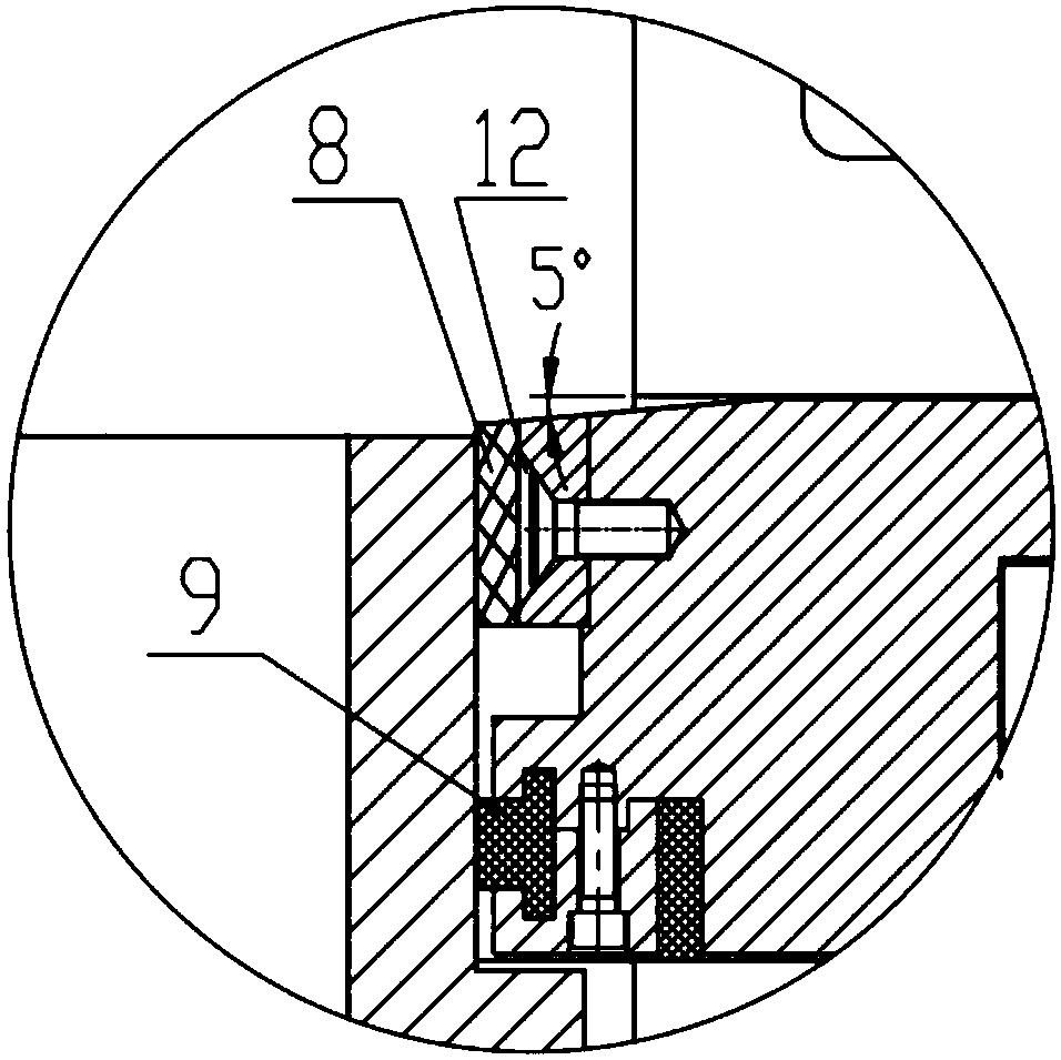
[0024] Such as Figure 1-4 As shown, it is an energy-saving combined pressure fracturing wellhead device of the present invention, which includes a hydraulic plate valve 1, a fracturing injection head 2, and a fracturing controller 3 connected in sequence. The fracturing controller 3 includes symmetrically arranged double gates Plate assembly, a channel through which the oil supply pipe hanger 4 passes is formed between the double ram assembly, the double ram assembly includes a half-sealed shell 5, and an upper ram 6 is arranged inside the half-sealed shell 5 and a The lower gate 7 below the plate 6, the end of the upper gate 6 is provided with slips 8 and the first sealing member arranged under the slips 8, the second seal is provided on the lower gate, and the upper gate 6 and the lower flashboard 7 can offset against the tubing hanger 4 under the promotion of the oil cylinder assembly.

[0025] The first seal includes a plane seal 9 and a top seal 10, the plane seal 9 and...


PUM


Abstract

The invention discloses an energy-saving pressure-combining well head fracturing device, relating to the technical field of oil field development. The device comprises a hydraulically-driven flat valve, a fracturing injection head and a fracturing controller, both of which are orderly connected. The fracturing controller comprises double-gate-disc assemblies which are symmetrically arranged. A passage allowing an oil pipe suspension device to pass through is formed between the double-gate-disc assemblies which comprise semi-sealing housings. The insides of the semi-sealing housings are equipped with upper gate plates and lower gate plates below the upper gate plates. End parts of the upper gate plates are equipped with clamp tiles and first sealing parts below the clamp tiles. Second sealing parts are arranged on the lower gate plates. Under push of an oil cylinder assembly, the upper gate plates and the lower gate plates can be abutted against the oil pipe suspension device. A well head fracturing device and an under-pressure operation device are integrated in order to prevent floating. The device is reliable in sealing performance, great in load weight, compact in structure and convenient in operation and can observe on-off positions of gate plates in a real-time manner.

Description

technical field [0001] The invention relates to the technical field of oilfield development, in particular to an energy-saving pressure-combined fracturing wellhead device. Background technique [0002] During the downhole operation of the oil field, the hot fracturing controller (also known as blowout preventer) is mainly used for hot fracturing construction, directly connected to the KY65 / 25 oil production wellhead cross, and cooperates with the fracturing tubing hanger to realize hanging fracturing. The function of cracking the pipe string, preventing the rotation and lifting of the pipe string, and at the same time realizing the well control function with the high-pressure hydraulic control assembly can achieve the purpose of shortening the construction period and reducing safety risks. The original pressure equipment was removed before the fracturing operation. Reinstalling after fracturing is time-consuming and laborious, and there are many safety hazards when operatin...

Claims


Application Information

Patent Timeline
Patent Type & Authority Applications(China)
IPC IPC(8): E21B43/26E21B33/06
CPCE21B33/06E21B43/26
Inventor 徐立监
Owner YANCHENG SUNDA PETROCHEMICAL MASCH CO LTD
Learn More