
A technology for continuous pneumatic conveying of powder materials

A powder material, pneumatic conveying technology, used in conveyors, conveying bulk materials, transportation and packaging, etc., can solve the problems of many automatic adjustment valves, poor feeding, high operating frequency, and reduce equipment investment and operating costs. , The effect of reducing equipment investment and saving electricity

Active Publication Date: 2016-11-23
LIAOCHENG LUXI CHEM ENG DESIGN
View PDF6 Cites 2 Cited by
  • Summary
  • Abstract
  • Description
  • Claims
  • Application Information

AI Technical Summary

Problems solved by technology

[0002] At present, the powder pneumatic conveying system occupies a very important position in today's industrial production process, but there are many problems in the existing powder pneumatic conveying system, for example, there are many equipments in the existing powder pneumatic conveying system, There are many automatic adjustment valves, high operating frequency, and gas support, resulting in poor feeding, complicated control system, and continuous material transportation. In order to improve the problems in the above-mentioned transportation methods, it is urgent to find a transportation method that can Realize continuous conveying and reduce equipment investment and system operation cost

Method used


Image

  • A technology for continuous pneumatic conveying of powder materials
  • A technology for continuous pneumatic conveying of powder materials
  • A technology for continuous pneumatic conveying of powder materials

Examples


Embodiment Construction

[0021] The present invention will be further described below in conjunction with the accompanying drawings and embodiments.

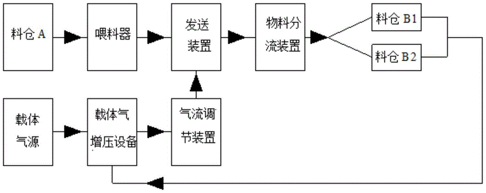
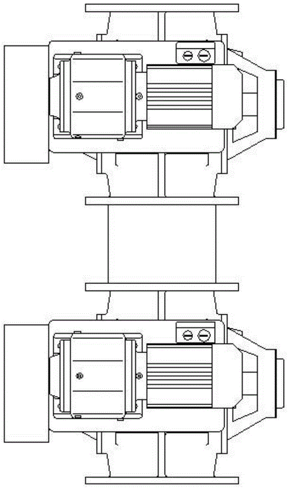
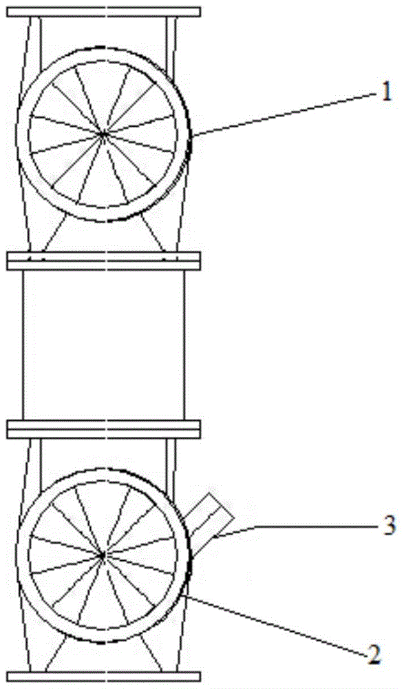
[0022] A process for continuous pneumatic conveying of powder materials, such as Figure 1-5 As shown, the easily oxidizable powder material from silo A is transported to the material delivery device after passing through the feeder, and the nitrogen gas output from the nitrogen source is pressurized by 0.35MPa through the carrier gas booster device, and then passed through the airflow adjustment device and the powder material At the same time, it enters the sending device. In the sending device, the powder material is transported to the material splitting device by nitrogen gas and then sent to different receiving bins B1 and B2 respectively. The nitrogen gas is discharged from the top of the receiving bin B1 and B2 and enters the carrier gas booster. Pressurize the equipment and return it to the system.

[0023] The powder material enters the upper v...


PUM


Abstract

The invention discloses a process for continuous pneumatic conveying of powder materials. The powder materials from silo A are transported to a material delivery device after passing through a feeder, and the carrier gas output from a carrier gas source is pressurized by a carrier gas booster device. , and then enter the sending device at the same time through the airflow adjustment device and the powder material. In the sending device, the carrier gas is used to transport the powder material to the material splitting device and then respectively sent to different receiving bins B1 and B2. The carrier gas is sent from the receiving bin The tops of B1 and B2 are discharged, enter the carrier gas pressurization equipment and return to the system after pressurization; the beneficial effects of the present invention are that the process is simple, the automatic adjustment is simple, the equipment investment is small, and it can not only continuously and stably transport powdery material products, Moreover, the efficiency of the whole device can be improved. In the long run, it can reduce the transportation cost of powder materials and increase the benefits of enterprises.

Description

technical field [0001] The invention relates to a process for continuous pneumatic conveying of powder materials. Background technique [0002] At present, the powder pneumatic conveying system occupies a very important position in today's industrial production process, but there are many problems in the existing powder pneumatic conveying system, for example, there are many equipments in the existing powder pneumatic conveying system, There are many automatic adjustment valves, high operating frequency, and gas support, resulting in poor feeding, complicated control system, and continuous material transportation. In order to improve the problems in the above-mentioned transportation methods, it is urgent to find a transportation method that can Realizing continuous conveying can reduce equipment investment and system operation cost. Contents of the invention [0003] The purpose of the present invention is to overcome the shortcomings of the above-mentioned prior art and...

Claims


Application Information

Patent Timeline
Patent Type & Authority Patents(China)
IPC IPC(8): B65G53/06B65G53/46B65G53/66B65G53/50
Inventor 肖光方占珍蒋东玉袁甫荣管艳华李红王延峰韩士亮杨海菲张星星王艳春何凯
Owner LIAOCHENG LUXI CHEM ENG DESIGN
Learn More