Long-distance small displacement detecting method based on microwave signals

A microwave signal and micro-displacement technology, applied in the direction of measuring devices, using wave/particle radiation, instruments, etc., can solve the problems of high precision and long distance, low cost, inapplicability, and high price, and achieve low cost and applicable Strong performance and high measurement sensitivity

Active Publication Date: 2018-12-11
ZHEJIANG UNIV
View PDF6 Cites 7 Cited by
  • Summary
  • Abstract
  • Description
  • Claims
  • Application Information

AI Technical Summary

Problems solved by technology

In the field of modern measurement and control technology, although the laser displacement detection method has become the main means of most structural displacement information detection due to its advantages of non-contact and high sensitivity, it is still unable to solve the problem of high precision, long distance and low cost in the process of displacement measurement. conflict between
The laser needs a lot of power to maintain high concentration during long-distance transmission, and the price of existing high-precision lasers is generally high
In addition, laser detection is not suitable for occasions with medium occlusion
However, in long-distance detection, the appearance of obstacles is often unavoidable

Method used


Image

  • Long-distance small displacement detecting method based on microwave signals
  • Long-distance small displacement detecting method based on microwave signals
  • Long-distance small displacement detecting method based on microwave signals

Examples


Embodiment Construction

[0021] The implementation process of the present invention will be described in detail below in conjunction with the drawings in the embodiments of the present invention.

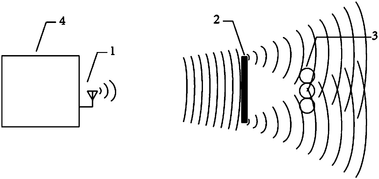
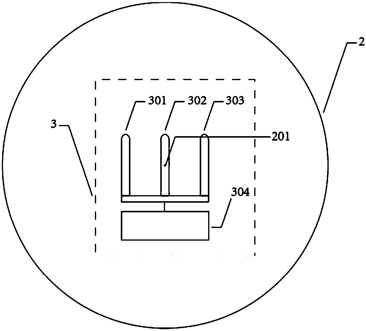
[0022] Such as figure 1 As shown, the present invention includes a microwave transmitter 1 with a microwave emission function, a metal circular barrier 2 with a microwave shielding function, and a microwave signal receiving device 3 with a function of measuring microwave intensity and position change; the microwave transmitter 1 is installed on the measurement target On the object 4, the microwave transmitter 1 and the microwave signal receiving device 3 are respectively arranged on both sides of the metal circular barrier 2, the metal circular barrier 2 is placed at a distance, and the microwave signal receiving device 3 is installed on the metal circular barrier 2 away from the microwave side of transmitter 1. A microwave transmitter 1 installed on the measurement target object 4, a metal circular barrie...


PUM


Abstract

The invention discloses a long-distance small displacement detecting method based on microwave signals. A microwave transmitter is fixed to a measured target object and moves along with the measured target object. The microwave transmitter emits a microwave signal to bypass a metal circular barrier, and then a microwave signal receiving device performs microwave detection. The microwave signal receiving device includes first, second and third receiving antennas and a receiving detecting circuit. The second receiving antenna is placed at a determined Arago point formed by the diffraction of themicrowave signal bypassing the metal circular barrier. The signal amplitudes and the phase differences of the receiving antennas are compared to obtain the small displacement of a microwave source less than the wavelength scale. The signal amplitudes, phases and frequencies of the receiving antennas are compared to obtain the amplitude and the frequency of the micro vibration of the long-range microwave source smaller than the wavelength scale. The method is suitable on occasions where an optical method cannot be used, is low in cost, high in measurement sensitivity, simple in system deployment, and good in applicability.

Description

technical field [0001] The invention relates to a detection method for a sub-wavelength micro-displacement of a long-distance microwave source, in particular to a detection method for a long-distance micro-displacement based on a microwave signal. Background technique [0002] With economic development and technological progress, there are more and more applications of engineering structures at all levels of society. Without exception, these systems require accurate monitoring technology to ensure their reliability, which also forces the detection technology to develop in the direction of high precision, long distance and low cost. In the field of modern measurement and control technology, although the laser displacement detection method has become the main means of most structural displacement information detection due to its advantages of non-contact and high sensitivity, it is still unable to solve the problem of high precision, long distance and low cost in the process o...

Claims


Application Information

Patent Timeline
Patent Type & Authority Applications(China)
IPC IPC(8): G01B15/00
CPCG01B15/00
Inventor 吴周祎皇甫江涛谷之韬
Owner ZHEJIANG UNIV
Why Eureka
Try Eureka