A system and method for calibrating body membranes with CT parameters and calibrating CT parameters

A technology of parameter calibration and calibration parts, which is applied in the direction of instruments, measuring devices, scientific instruments, etc., can solve the problems of low calibration accuracy and poor stability of CT parameters, so as to improve the calibration accuracy and stability, strengthen the difference between light and shade, and the projection area clear effect

Active Publication Date: 2020-11-13
WUHAN UNIV OF SCI & TECH
View PDF4 Cites 0 Cited by
  • Summary
  • Abstract
  • Description
  • Claims
  • Application Information

AI Technical Summary

Problems solved by technology

[0006] The technical problem to be solved by the present invention is to provide a method for calibrating body membranes with CT parameters and CT parameter calibration for the problems of "artifacts" in the projection images of calibration body membranes in the prior art, which lead to low calibration accuracy and poor stability of CT parameters. System and CT parameter calibration method

Method used


Image

  • A system and method for calibrating body membranes with CT parameters and calibrating CT parameters
  • A system and method for calibrating body membranes with CT parameters and calibrating CT parameters
  • A system and method for calibrating body membranes with CT parameters and calibrating CT parameters

Examples


Embodiment 1

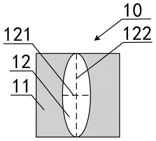
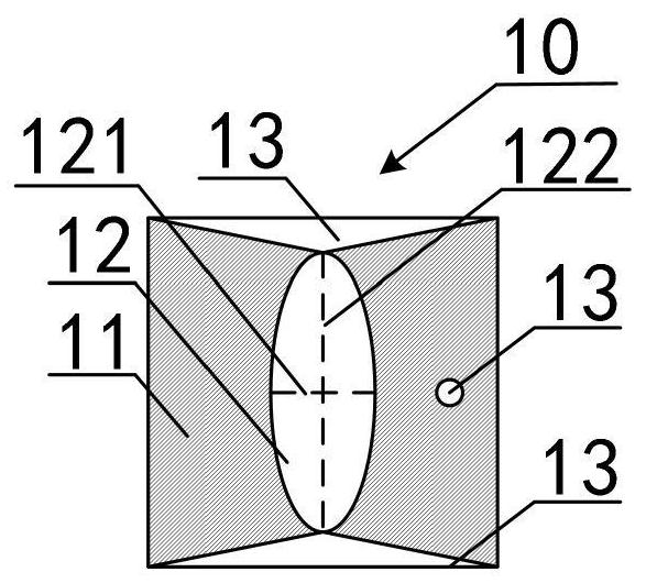
[0070] Such as figure 1 As shown, a CT parameter calibration phantom 10 according to the embodiment of the present invention includes: a light-shielding substrate 11 and a first transparent marker 12 arranged on the light-shielding substrate 11, the first transparent marker 12 has mutually orthogonal The first axis of symmetry 121 and the second axis of symmetry 122 .

[0071] The light-shielding substrate 11 can be made of sheet metal, the first transparent marking member 12 can be made of polyethylene plastic, and the first transparent marking member 12 can be glued on the surface of the light-shielding substrate 11 .

[0072] For example: the light-shielding substrate 11 is a square, and the side length of the square is 100 cm. The first transmissive marker 12 is an elliptical transparent marker. The minor axis of the elliptical transparent marker is the first axis of symmetry and the major axis is the second symmetry. axis, the length of the minor axis is 30cm, and the le...

Embodiment 2

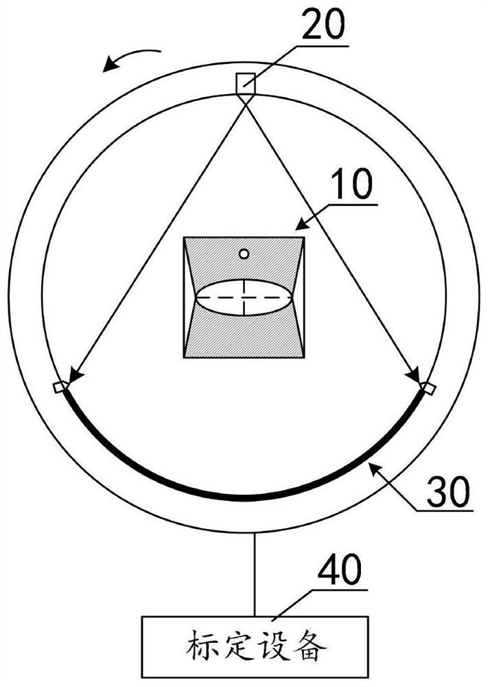
[0085] Such as image 3 As shown, a CT parameter calibration system according to an embodiment of the present invention includes: a CT parameter calibration phantom 10, and also includes: a ray emitter 20, a detector group 30 and a calibration device 40;

[0086] A ray emitter 20, configured to emit ray light to the CT parameter calibration phantom 10;

[0087] The detector group 30 is used to detect the ray light transmitted from the CT parameter calibration phantom 10 to obtain a projection data group;

[0088] The calibration device 40 is used to irradiate the CT parameter calibration body 10 in different projection directions through the ray emitter 20 to model the projection image, and mark the projection coordinates of the projection center in the projection image according to the first projection data set and the second projection data set ;

[0089] The relative positions of the ray emitter 20 and the detector group 30 are fixed, and the line connecting the center of...

Embodiment 3

[0135] Such as Figure 7 Shown, a kind of CT parameter calibration method comprises the following steps:

[0136] Step 110: Set up a CT parameter calibration body film between the ray emitter and the detector group with fixed relative positions. The CT parameter calibration body film includes: a first axis of symmetry and a second axis of symmetry that are orthogonal to each other and have different lengths. A light-transmitting fixed piece, the center of symmetry of the first light-transparent fixed piece passes through the line connecting the center of the ray emitter and the center of the detector group;

[0137] Step 120, the ray emitter emits ray light to the CT parameter calibration phantom;

[0138] Step 130: The detector group detects the ray light transmitted from the CT parameter calibration phantom to obtain projection data, and the projection data includes: the first ray light detected by the detector group when the ray light emitted by the ray emitter is parallel...


PUM

PropertyMeasurementUnit
radiusaaaaaaaaaa
lengthaaaaaaaaaa

Abstract

The invention relates to a CT parameter calibration phantom, a CT parameter calibration system and a CT parameter calibration method. The calibration phantom is formed by arranging a light-transmitting calibration member with two symmetrical axes orthogonal to each other on a light-shielding substrate, the calibration phantom is calibrated between a fixed position of a ray emitter and a detector group, and a center line of the ray emitter and the detector group passes through a symmetrical center of a first light transmitting calibrator; the CT parameter calibration phantom is illuminated through the ray emitter in different projection directions to construct a projection image, and the CT parameters are calibrated based on projection data detected by the detector group when the ray emitted by the ray emitter is parallel to each axis of symmetry. The CT parameter calibration phantom, the CT parameter calibration system and the CT parameter calibration method overcome an 'artifact' phenomenon existing in the projection image of the CT parameter calibration phantom, and improve the calibration precision and stability of the CT parameters.

Description

technical field [0001] The invention relates to the technical field of CT parameter calibration, in particular to a CT parameter calibration body membrane, a CT parameter calibration system and a CT parameter calibration method. Background technique [0002] The CT system is a detection system that constructs tomographic images of objects, and is widely used in technical fields such as industrial detection, medical diagnosis, and electron microscopy. [0003] As the working time of the CT system continues to increase, the light source and detector in the CT system are gradually aging, and the scanning parameters of the two are inconsistent. During the process of the detector detecting the projection data of the object, the projection data will be shifted, reducing the object’s accuracy. Projected image quality. [0004] In order to correct the projected image of the object, it is an effective way to use the calibration phantom to calibrate the projection data, specifically:...

Claims


Application Information

Patent Timeline
Patent Type & Authority Patents(China)
IPC IPC(8): G01N23/046
CPCG01N23/04G01N2223/03G01N2223/303
Inventor 张梦伟
Owner WUHAN UNIV OF SCI & TECH
Why Eureka
Try Eureka