Optical system based on multispectral imaging

A multi-spectral imaging and optical system technology, applied in the field of optoelectronic equipment, can solve problems such as viewing angle deviation, low quality of single imaging, loss of important monitoring information, etc., to achieve the effect of improving high functional density, ensuring imaging quality, and avoiding loss of targets

Active Publication Date: 2018-12-11
HUBEI HUAZHONG PHOTOELECTRIC SCI & TECH
View PDF7 Cites 2 Cited by
  • Summary
  • Abstract
  • Description
  • Claims
  • Application Information

AI Technical Summary

Problems solved by technology

[0004] The single-spectrum imaging lens in the prior art cannot meet the multi-functional requirements according to the needs of the public; the multi-camera type is composed of multiple cameras, and each camera is equipped with a different passband filter to obtain the corresponding band information respectively. The multi-spectral camera can realize the integration of maps, but there is a deviation in the viewing angle between cameras with different optical axes, which requires correction and matching of the viewing angles of the multi-channel images in the subsequent data processing; filter-type multi-spectral switching The lens solves the problem of multi-camera, but it cannot allow multi-spectral lenses to work at the same time, important monitoring information may be lost during the switching process, and the monitoring environment cannot be displayed in real time; the single-lens multi-channel splitting type uses a single lens plus splitting The prism divides light into multiple paths. Patent CN201010614376 discloses a single-lens multi-spectral imaging optical system. Although it solves the problem of loss of important monitoring information caused by multi-camera and switching, the quality of single imaging is not high

Method used


Image

  • Optical system based on multispectral imaging
  • Optical system based on multispectral imaging
  • Optical system based on multispectral imaging

Examples


Embodiment Construction

[0030] In order to make the object, technical solution and advantages of the present invention clearer, the present invention will be further described in detail below in conjunction with the accompanying drawings and embodiments. It should be understood that the specific embodiments described here are only used to explain the present invention, not to limit the present invention. In addition, the technical features involved in the various embodiments of the present invention described below can be combined with each other as long as they do not constitute a conflict with each other.

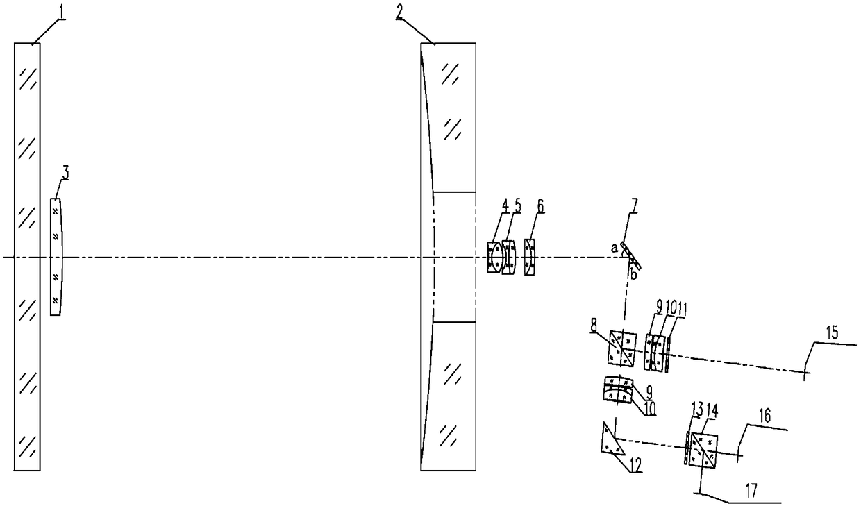
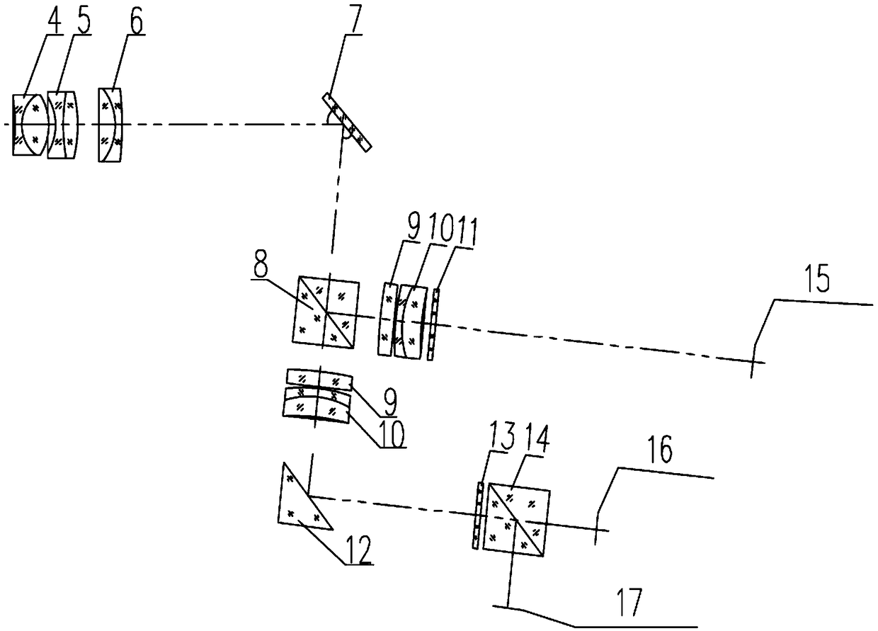
[0031] figure 1 It is a schematic structural diagram of an optical system based on multispectral imaging according to an embodiment of the present invention. Such as figure 1 As shown, the optical system based on multispectral imaging includes a primary reflector 2, a secondary reflector 3, a first cemented lens 4, a second cemented lens 5, a third cemented lens 6, an oscillating mirror 7, a f...


PUM


Abstract

The invention discloses an optical system based on multispectral imaging, which comprises a white light imaging CCD (15), a laser imaging CCD (16), a laser detector (17), a secondary mirror (3), a primary mirror (2), a first glued lens group and a pendulum lens (7), wherein the middle of the primary mirror (2) is provided with a hole matched with the secondary mirror (3); the path of light reflected by the pendulum lens is provided with a first dispersion prism (8), the path of the light passing through the first dispersion prism (8) is divided to two, one path is received by the white light imaging CCD (15), the other path of light is provided with a mirror (12), and a second dispersion prism (14) is arranged behind the mirror (12); and the laser imaging CCD (16) and the laser detector (17) are arranged on two light paths after light splitting of the second dispersion prism (14). The optical system based on multispectral imaging takes white light imaging, laser imaging and laser detection into consideration, and high imaging quality is ensured.

Description

technical field [0001] The invention belongs to the technical field of optoelectronic equipment, and more specifically relates to an optical system based on multispectral imaging. Background technique [0002] Multispectral imaging technology is a remote sensing technology that appeared in the early 1960s. The selection of its band range and number of bands is directly related to the application target. It is of great significance to improve the physical and chemical properties and improve the target recognition ability. Multi-spectral TV imaging technology is widely used in TV guidance and photoelectric reconnaissance. When observing and tracking targets, it can display images generated by visible light passing through the optical system. At the same time, it can also detect and image laser light at the same time. The high functional density and real-time performance of the system heighten the requirements. In order to ensure effective and timely high-definition imaging o...

Claims


Application Information

Patent Timeline
IPC IPC(8): G02B27/00G02B27/10G02B7/04G02B17/06G01J3/28G01J3/02
CPCG02B7/04G02B17/06G02B27/0025G02B27/10G01J3/0208G01J3/0213G01J3/2823G01J2003/2826
Inventor 韩志刚郑孟许志波皮雳王胜郝光宇张俊锋
Owner HUBEI HUAZHONG PHOTOELECTRIC SCI & TECH
Why Eureka
Try Eureka